I have had a luxurious summer break and haven’t touched the FPGA video synth for almost two months.
I want to wrap up the project. I’ve just looked through the blog to see what I can take from it :
- I want to expose the FPGA synth in its current state (with minimal or no modifications) at
TEI 25′(didn’t get accepted! Applying to DIS 2025 though)and in Xiao’s space(she doesn’t want electronics there). - I want to make a kind of research paper / presentation with the HDMI imbalance hack. This is the coolest, most unexpected thing I found and it absolutely requires the FPGA and knowledge of verilog. I don’t want to go further towards the engineering tasks I was engaged in, nor the superficial design activities.
Specificity, and its details, was one of the keys about writing good scripts for the Making of Sopranos documentary Wise Guy. For this reason I don’t think making a framebuffer and then seeing all the different ways I can modify a single input image really makes any sense, there are just too many possibilities and it is too general / too much of an engineering project. Remember this broken screen project with videos playing : https://haoni.art/spin-III.
I could see my series of “design research chapters” as being composed of a series of mini strategies :
- freezing a single computer in time by stretching it up (prepared plotter, prepared 3D prints)
- one input, many different interpretations because machines are idiosyncratic (prepared CRT controller)
- the world view of the computer program (Revit internal IDs)
The natural things to test would be :
- How can I mess with the HDMI color balance, what is the range of possibilities trying different imbalances ?
- How do different screens react ?
- Could this be a kind of hacking of various video protocols like VGA, DVI and HDMI ?
More thoughts on the state of the project :
There is something cheap about putting images on screens, it’s so easy and it’s so ubiquitous that it doesn’t feel special or difficult to do or in any way sacred. At the same time, following the project where it wants to go, I want to work with video because I can with my modest tech skill level.
My video experiments have taught me a few things :
- For abstract animations, bit patterns are cool for digital and simple filters and oscillators are cool for analog. In the spirit of the latter experiments, I made a series of hand-made, wooden-based, simple filters that seemed like a conclusion in themselves. Beyond these it risks getting into very common computer science art territory around math (fractals, etc.) that you can see on shadertoy and processing. From doing p5js workshops (and NO SCHOOL telling me that hardware workshops are always the most enjoyed) I can say that playing with hardware is just more fun than making animations with code.
- Taking iconic cinema as input immediately seems richer, because there is culture and history involved, though I can’t say exactly why I should be distorting a film from the 1960s. Using memory to store video clips in hardware was a breakthrough for me, the severe limitations of SRAM were a useful creative constraint. I haven’t yet been able to take in a video stream and modify it live with the FPGA filters though the VGA camera could be a good solution for that and could lead to new tests.
- On applications : I don’t appear to want to make a cute product : too much polishing, purely technical work, admin and marketing, not enough fun and “design research”. On the other hand, my situation at work allows me to spend money on boards and components so I feel I should take advantage of the opportunity to test ideas in physical form. Hardware video workshops are cool and can work; I’ll test my first technical FPGA workshop in January. I am not sure what to say about this project if I were trying to write a paper. I don’t know if I want to fully engage with the VJ community as I don’t feel part of the music scene. Therefore the project remains hovering between a DIY / hobbyist open-source hardware art project, which doubles as a project to learn technical things, as well as a curated set of images and animations of my “design research” posted on Instagram. In other words, it has to be visually and technically interesting to me.
***************
Reviewing 20th C artists, some notes :
- Some of Duchamp’s readymades were actually called “assisted readymades” if they were altered.
- Décollage like the artwork 122 rue du Temple is an example of ripped collage.
- I feel more aligned with the Bauhaus (Anni Albers, László Moholy-Nagy) than NY based conceptual or minimalist artists.
- Some quotes : Albers “Technique was acquired as it was needed and as a fondation for future attempts. Unburdened by any practical considerations, this play with materials produced amazing results, textiles striking in their novelty, their fullness of color and texture, and possessing often barbabic beauty”. She produced “prototypes for industrial production”.
- MOMA Highlights on Moholy-Nagy : Abstraction is rare and often boring in photography, more interesting is an unfamiliar configuration of form competes for our attention with the subject (between figurative and abstract). Photography is objective, and its unpredictability unveils fresh experiences. Photography challenges old habits of seeing by showing very distant or very small things, or for looking up or down. Photography has revolutionized modern vision.
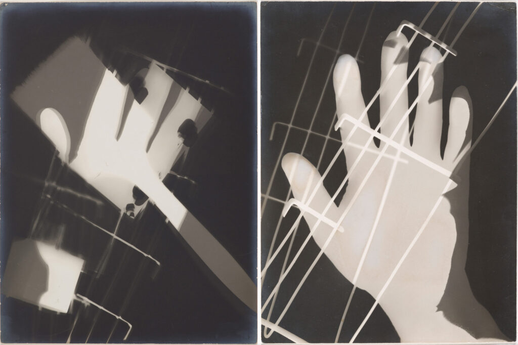
- Man Ray Rayographs : “It is impossible to say which plane of the picture are to be interpreted as existing closer or deeper in space. The picture is a visual invention, an image without a real-life model to which we can compare it.” His Rayographs were unpredictable pictorial adventure.
- MOMA Highlights on Stan Brakhage : “In Brakhage’s hands [directly manipulating film stock] became a way to maintain a direct experiential relationship with his chosen medium while refining his art to the essential elements.”
- Add to the video reel : Eisenstein, Man with a movie camera, voyage à la lune, raging bull.

**************
There is another path forward, making an FPGA LVDS LCD controller board. I like that this would be following the logic of the project, going deeper and not running away from the challenge. On the other hand, I’m not convinced it gets much deeper than VGA or HDMI as I’m still dealing with rows and columns, H and V syncs, and colors. It is also potentially a technical hassle like the SD card headache.
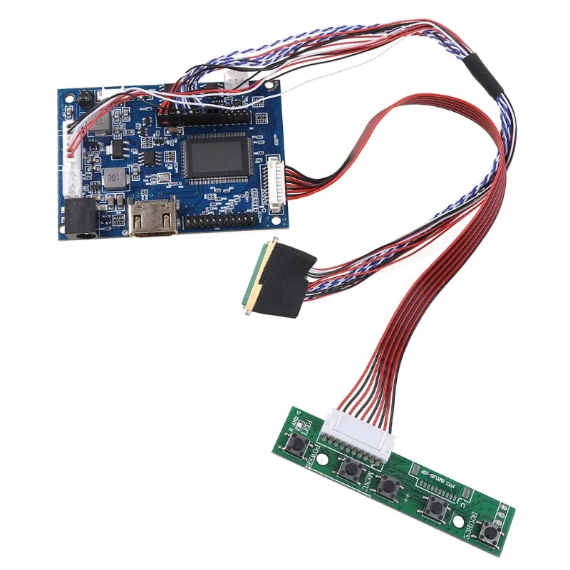
You can already see some new colour and texture effects in this DIY project (https://community.element14.com/products/devtools/avnetboardscommunity/b/blog/posts/driving-a-laptop-lcd-using-an-fpga) :


Here are some resources for controlling a Flat panel display (AKA making a FPD-Link converter) with FPGA:
http://web.archive.org/web/20160109020747/http://g3nius.org/lcd-controller/
https://www.martinhubacek.cz/blog/lvds-lcd-hacking-with-fpga/
https://community.element14.com/challenges-projects/project14/programmable-logic/b/blog/posts/paneldriver-a-fpga-based-hdmi-to-fpd-link-converter
https://community.element14.com/products/devtools/avnetboardscommunity/b/blog/posts/driving-a-laptop-lcd-using-an-fpga
It looks like these are some examples of the typical signal setups (JEIDAVESA?) :
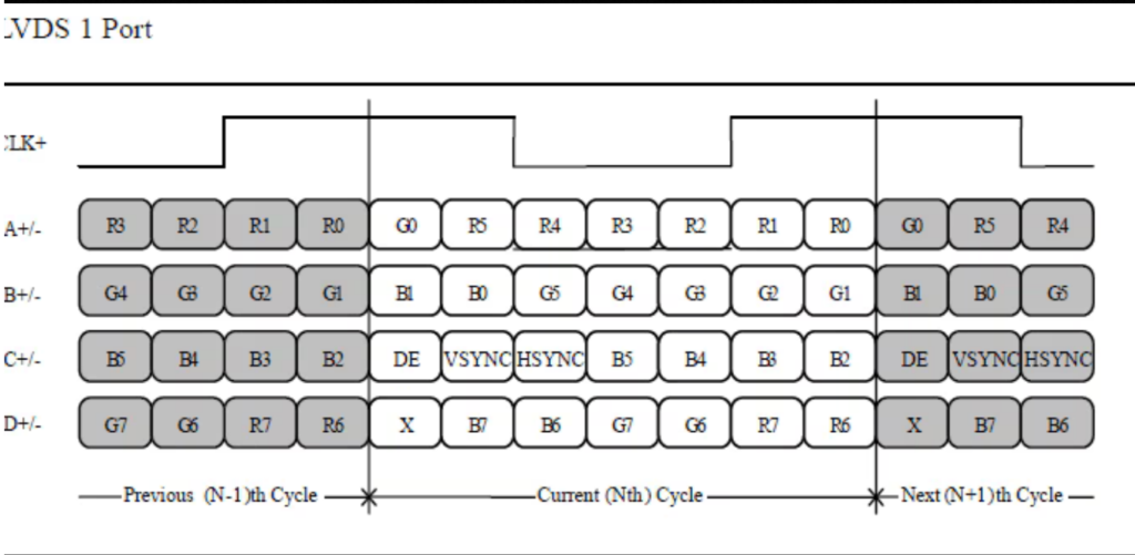

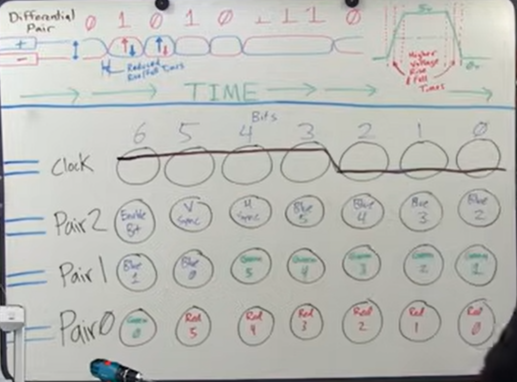

*****************
Yet another path forward is to complete the tests with the VGA camera input. Check out the pocket glitchomatic which has a camera (solves all the issues with taking video in!!!!)
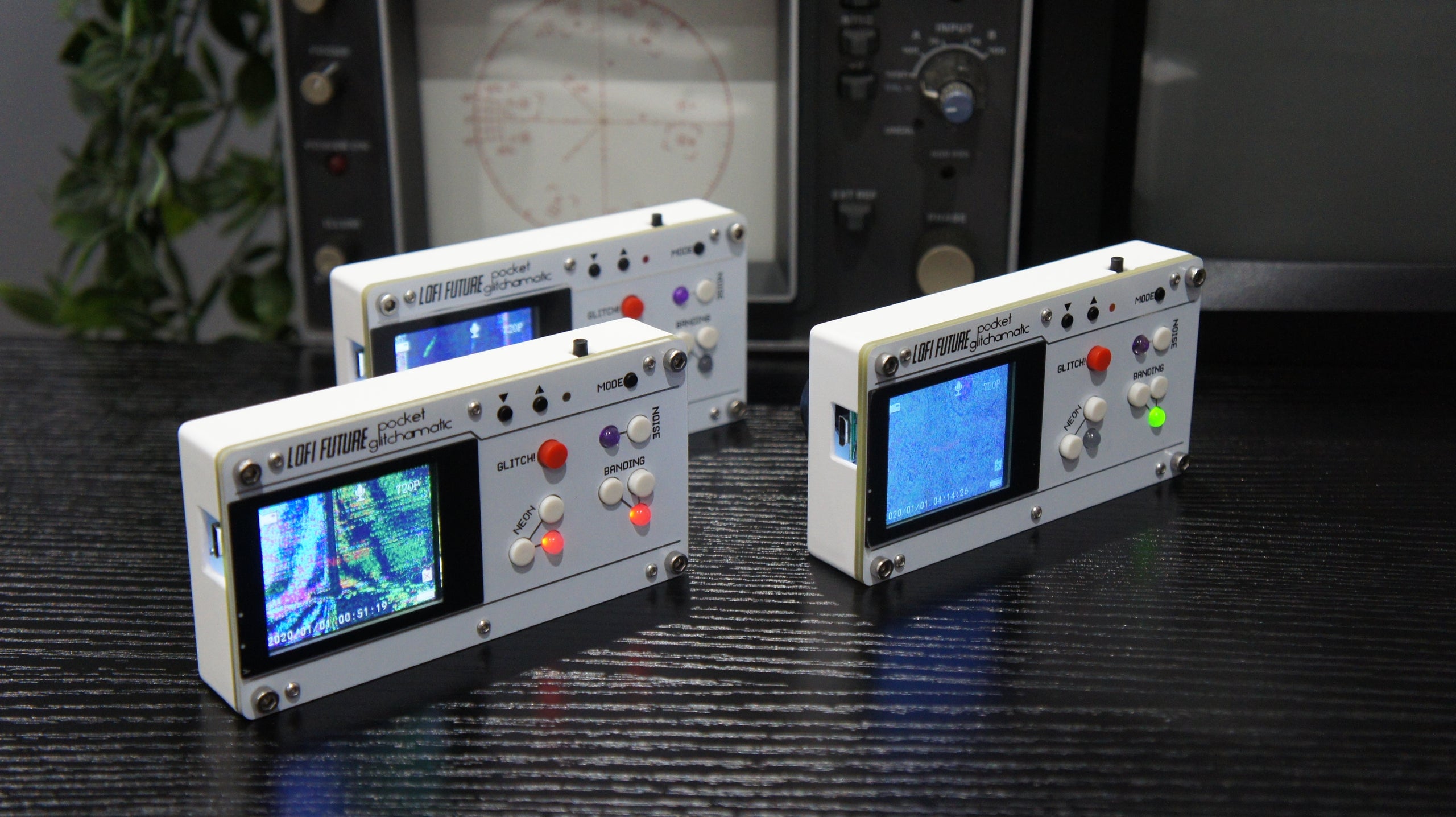
and this camera called pixless on kickstarter :

This could work nicely with the code I was preparing where each combination of 8 bits selects different logic operations !
Circuit bent digital cameras by glitchedbyproxy :

Then again, couldn’t I just have a webcam on the rpi and output VGA ? No annoying configuration necessary for the camera ! Isn’t the real thing to learn here how to do convolution with the FPGA?
And some cool automata work here by Richard Palethorpe https://richiejp.com/1d-reversible-automata

********
OK, I am trying now to pick back up where I left off pre-summer, notably trying to save rpi video into SRAM through the FPGA in a stable way.
Trying to get the CC version of the board (with SRAM, buttons and RPI dock) back up to speed. I soldered VGA connector and added VGA pins to various .pcf had lying around. None appear to produce anything on the screen. EDIT : This was a pin constraints error. Looked on the scope and the pins weren’t doing anything. It looked at only one of the three input verilog files and ignored the pins from the others. ALWAYS CHECK THE PIN CONSTRAINTS, EVEN IF YOU MAKE A PCF !! This is the issue where IceCube2 can’t seem to deduce the hierarchy of the files and determine which one is TOP. Look at the file name of the bitmap, it should be the top file. Also, be suspicious if it takes too little time to synthesize ! The second issue I had was the vga_sync module not using the incoming clock (instead taking an output from a pll that had since been removed), so nothing was happening.
The rpi is now outputting 640×480 in DPI mode @ 32MHz, I checked on the scope. I think the easiest would be to get the rpi at the same timing. I would like to try again to run custom timings as this appears easier than modifying my fragile FPGA verilog code. (I have forgotten how to get a PLL running). EDIT : I am looking at how the Alhambra sets up a PLL and I’m just editing his pll file with different values : https://github.com/imuguruza/alhambra_II_test/blob/master/vga/vga_test/pll.v. This appears to work stably for turning 12MHz to 25MHz but when I try 100MHz to 32 MHz I run into issues (though perhaps I should just divide the clock in verilog?). I would love to get this rpi DPI calculator working https://nerdhut.de/software/raspberry-pi-dpi-calculator/ or learn to use the new way rpi encodes the screen timings. EDIT : got the rpi DPI calculator installed :
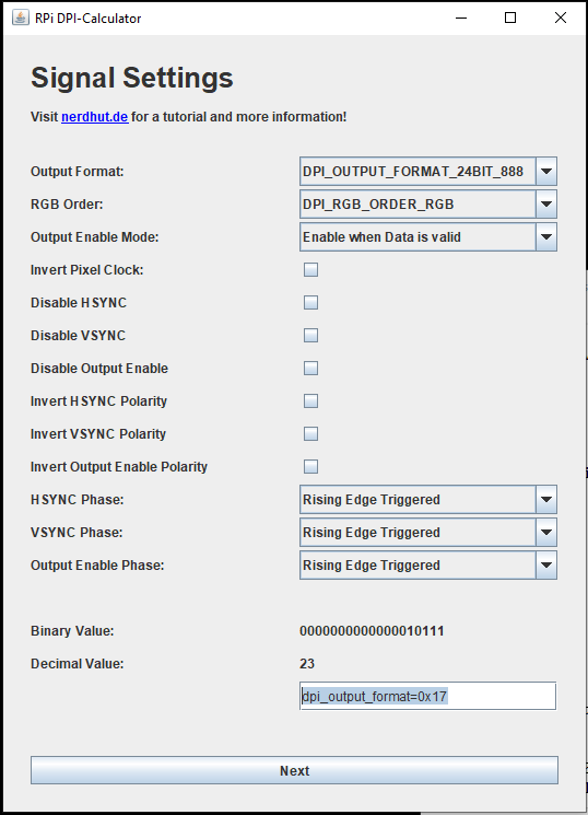
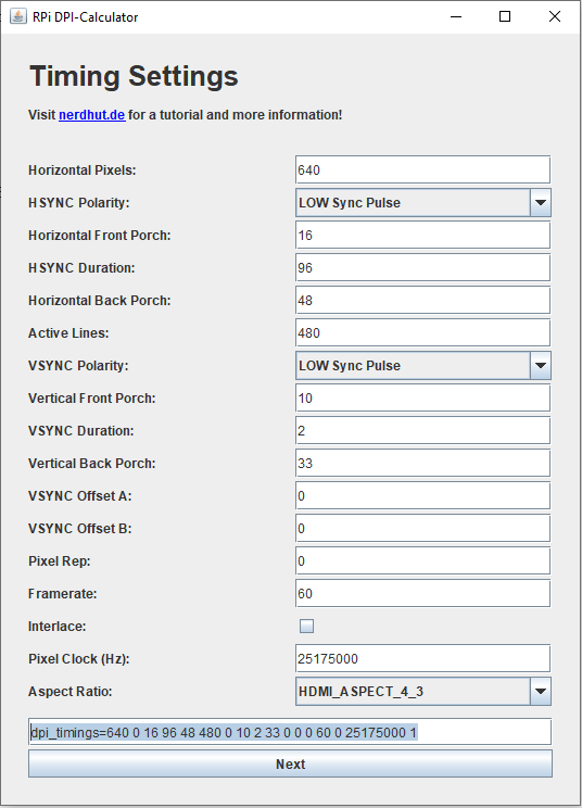
Unfortunately the first try (above) hasn’t yet worked on the rpi (it doesn’t show any pin activity on ‘scope). The best thing working is still the 640×480 at 32MHz with this end of the config :
gpio=0-9=a2
gpio=12-17=a2
gpio=20-25=a2
gpio=26-27=a2

dtoverlay=dpi24
enable_dpi_lcd=1
display_default_lcd=1
dpi_group=2
dpi_mode=87
dpi_output_format=516118
dpi_timings=640 1 44 2 42 480 1 16 2 14 0 0 0 60 0 32000000 1
So how can I divide my FPGA clock from 100MHz to 32MHz ? Tried creating a counter that counted up to 64 MHz and toggled another counter, but I didn’t get any video output (too lazy to debug).
I have a new timing which works (at least on the ‘scope) on the rpi to output 50MHz 800 x 600 :
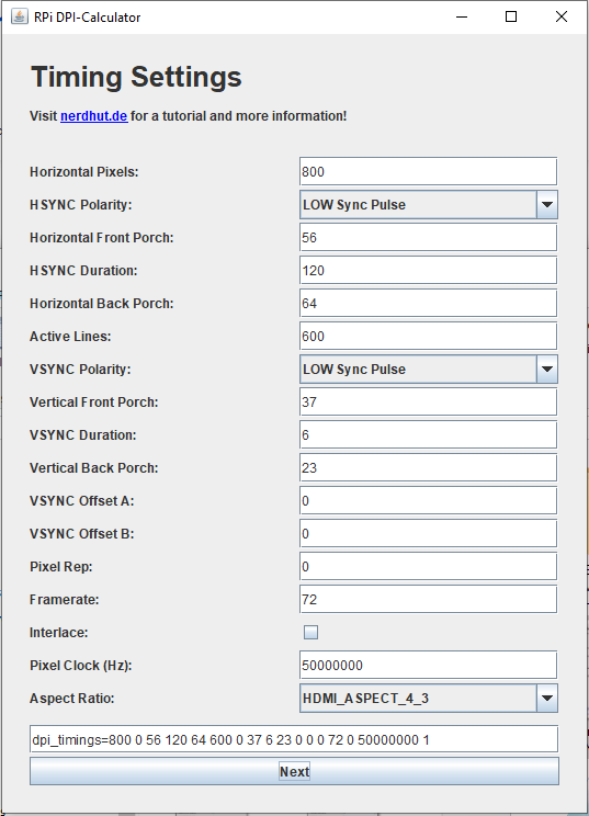
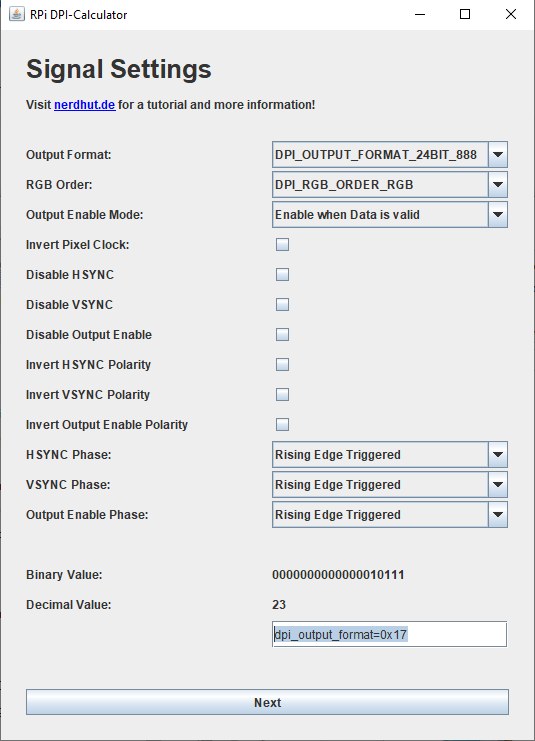
So here are the two important lines :
dpi_output_format=0x17
dpi_timings=800 0 56 120 64 600 0 37 6 23 0 0 0 72 0 50000000 1
Now I will try to get the FPGA to output these timings…And it works at 800×600 @ 50MHz !
So here are the modifications I made to the vga_sync_test file :
localparam h_pixel_max = 800;

localparam v_pixel_max = 600;

localparam h_pixel_half = 400;

localparam v_pixel_half = 300;

...

// for a 50MHz clock we divide 100MHz by 2

reg [1:0] clk_div = 0;

always @(posedge clk_in)

begin

clk_div <= clk_div + 1;

end
...


vga_sync vga_s(

.clk_in(clk_div[0]), //Dividing by two gives 50MHz

.h_sync(h_sync),

.v_sync(v_sync),

.h_count(h_count),

.v_count(v_count),

.display_en(display_en) // '1' => pixel region

);

endmodule
And the modifications to the vga_sync file :
module vga_sync(
input wire clk_in,
input wire reset,
output reg h_sync,
output reg v_sync,
output wire clk_sys,
output reg [10:0] h_count,
output reg [9:0] v_count,
output reg display_en,
output wire locked
);

wire locked;
wire sys_clk;

// Pixel counters
reg [10:0] h_counter = 0; // NEED 11 BITS NOW TO REPRESENT THE VALUE 1040 !!!
reg [9:0] v_counter = 0;

localparam h_pixel_total = 1040;

localparam h_pixel_display = 800;

localparam h_pixel_front_porch_amount = 56;

localparam h_pixel_sync_amount = 120;

localparam h_pixel_back_porch_amount = 64;

localparam v_pixel_total = 666;

localparam v_pixel_display = 600;

localparam v_pixel_front_porch_amount = 37;

localparam v_pixel_sync_amount = 6;

localparam v_pixel_back_porch_amount = 23;
***********
There are some reasons to remake the CC SRAM board. I guess this shows I am doing incremental design, probably with the hope that this could be a product still one day. Perhaps I should tell myself that I am making a single version change per year ? :
- The spot where the rpi plugs in blocks the programming pins and the SD card hits the VGA connector.
- A reset button !!!
- 2 pin DPI switch to load different images into FLASH
- Sending rpi_pixel clock to a BUFFERED input on the FPGA (like I am currently doing with the 100MHz clock to pin 49)
- A bigger (and FASTER, like 10ns) SRAM
- Two boards, one with keys, another with circuit. This gives me more space to add things, removes the constraints of the holes passing through the board, gives more buttons, tighter spacing (much more satisfying than the spaced out keys currently), gives it more heft, feels more like a real tool and less like a toy.
- The rpi needs its own power and the power plug can’t currently fit on when it is plugged in. Either I supply the power for the rpi or it is externally powered and I accomodate the plug.
- Currently I am only taking 4 pins from the rpi but ideally I would take 12 color input pins. I also should have h sync, v sync, and DEN wired directly from rpi to FPGA.
- Possibly add a track ball mouse ?
- It would be smart to look into how the rpi camera could be integrated into the design.
- Presumably I will want to move beyond 1280 logic gates to the 4K once I’ve done more tests ?
- Make it so that the Lattice programmer plugs in easily and can’t be plugged in wrong
Another insight : so much time is wasted setting up and resetting up the same setup. Having a permanent version of the screen + cable + rpi + FGPA combination with the wires not moving is going to be essential if I am to actually develop this further. I must switch to seeing this project as a long term one, and I must take my time and do things properly. I should program in reusable modules too !
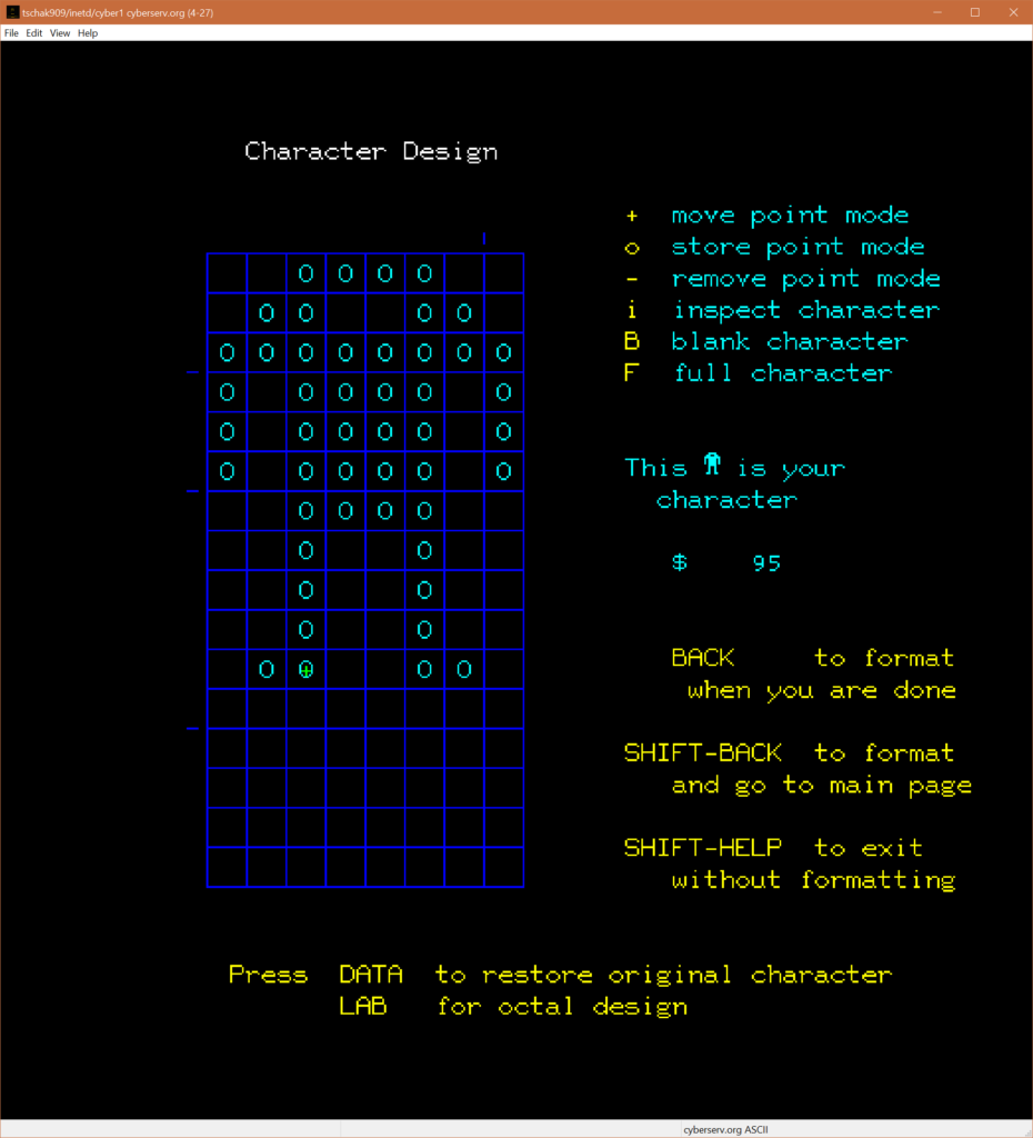
How cool would it be to have an interface like this on the FPGA :
********
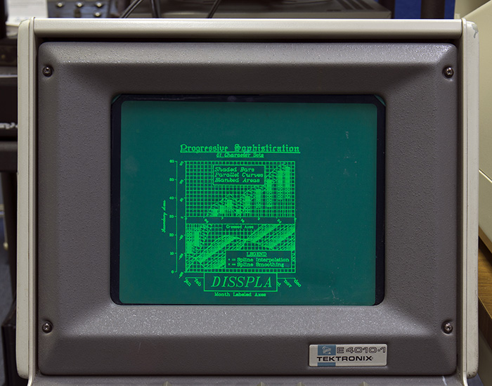
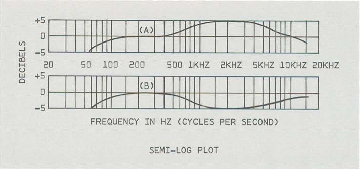
Check out these retro Tectronics screen images :
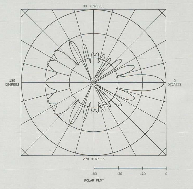
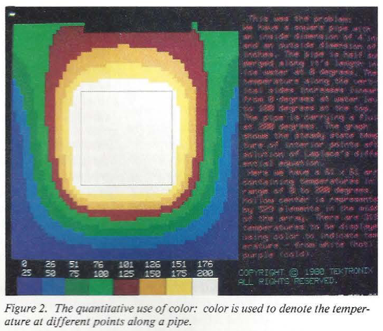
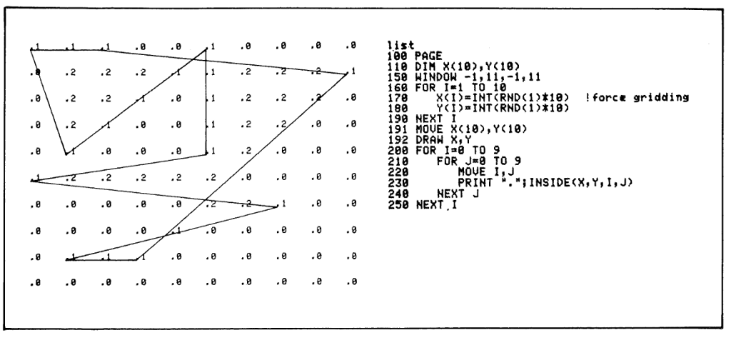

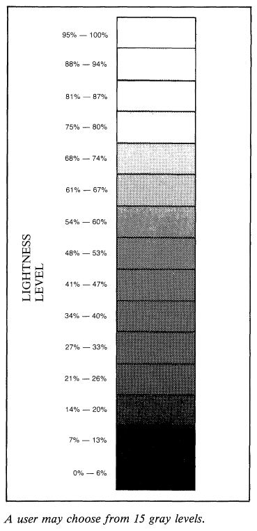
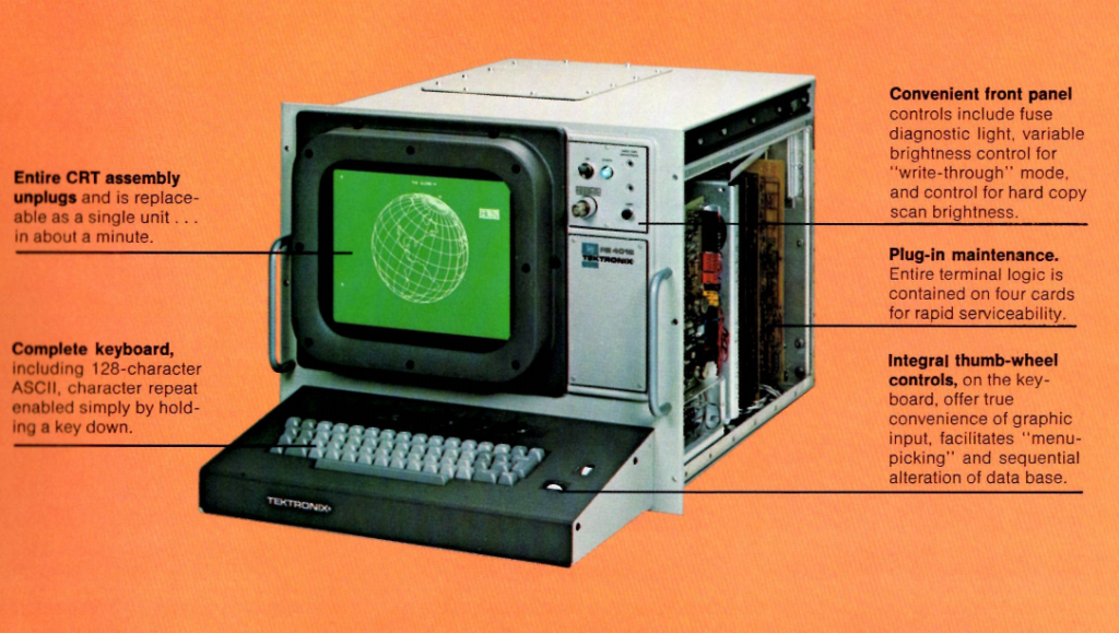
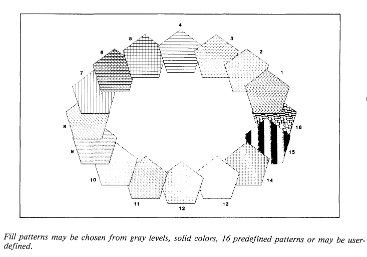
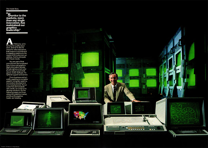
******
Just trying to make my life easier :
The rpi takes about 2 minutes to enter into video mode in DPI.
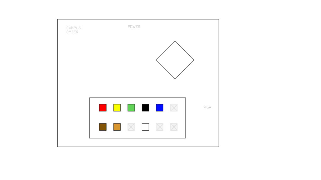
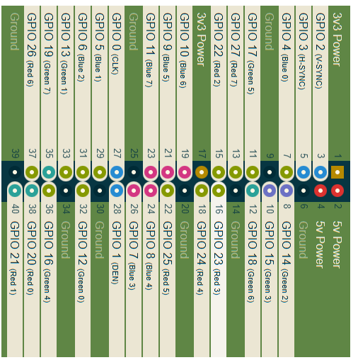

I am also being really careful each time I make something worth saving, because IceCube2 edits the files you load, I am making sure to copy and save the files (all verilog files + pcf) I want to keep and to name them so that it is clear what they do. With this structured approach I can build atop my previous work. EDIT : Tommy suggested the obvious : use a git ! Transitioning to this work flow now…Everything is going here :
https://github.com/preparedinstruments/bechamel/tree/main/verilog
I can record from the VGA into SRAM and keep the image mostly frozen. Here is the key line (that basically says only increment the SRAM address if we are in the active pixel area, and also divide it by 2 because the SRAM is only 256K and the total pixels are 480K, and restart the SRAM address counter at the end of the screen) :
always @(posedge clk_div[1]) begin

if (display_en) begin
if( addr < 17'b11111111111111111 && h_count > h_pixel_front_porch_amount && v_count > v_pixel_front_porch_amount && h_count < h_pixel_display && v_count < v_pixel_display && h_count[0]==1 && v_count[0]==1) begin // basically divide the counters because there are 480K pixels but I have 256K SRAM, and only count the active pixel area
addr <= addr+1;
end
else begin
addr <= 0; // I want to restart the counter at the end of each screen draw ?
end
end
end
It produces stable recordings, but they are imperfect :
input

output

So far it’s only working well with vertical lines though…EDIT fixed that !
Instead of incrementing the address, I am now taking the pixel position as the address.
addr <= h_count + (v_count*h_count);Very noisy but the image is frozen solid with no movement ! But wait, this is wrong because it should be
addr <= h_count + (v_count*800);EDIT : What seemed like success was in fact failure, I only had stable lines because I was recording only the first line and then resetting the SRAM addr to zero. I fixed that by only making the addr zero once I had reached the v_lines_max. I am getting sketchy recordings but I think it’s because the video is at 50MHz and the memory can’t go that fast?
********
Rereading these Project F FPGA graphics tutorials three things :
- You need to account for memory latency with an offset which you determine through testing when using a framebuffer
- A linebuffer saves you from doing too much memory access
- Shouldn’t calculate the pixel position by multiplying the horizontal_line_count + (vertical_line_count * horizontal_line_width) but should increment the addr value.
*****
I think to get recording w SRAM working I need to first record (and display, and clock the SRAM) with the input pixel clock + h&v syncs, and then switch to playback (and display, and SRAM clocking) with instead the FPGA board clock.
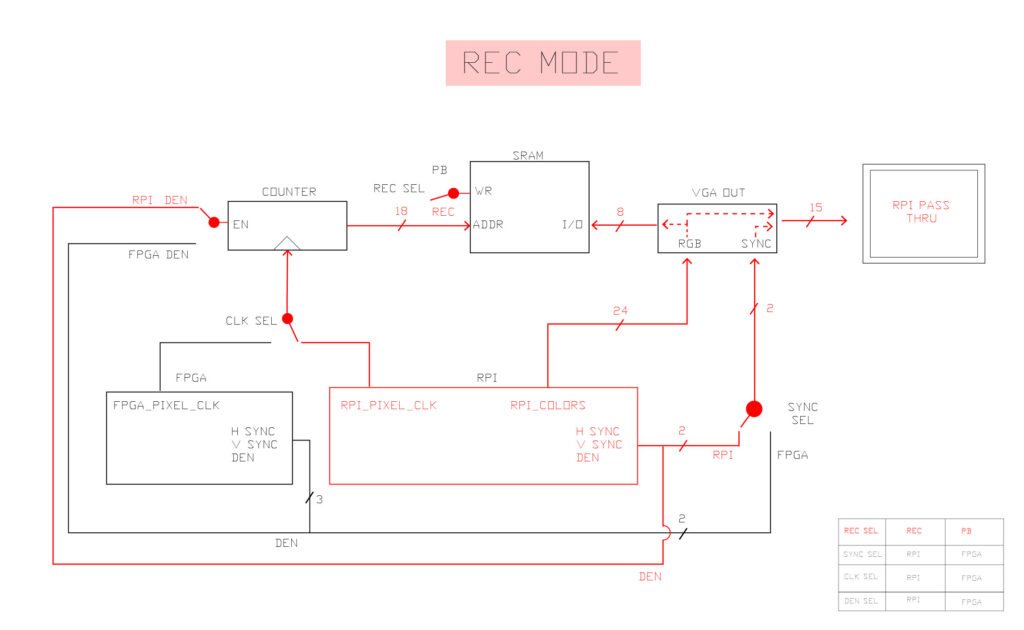
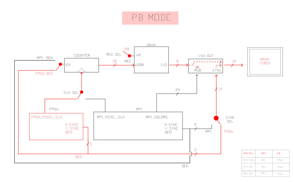
Another option might be to use PLL to synchronize external clocks that are out of phase somehow ? Also, if the clock and the incoming data are not synchronized, it is apparently not optional to double flop the input signal.
Some memory tests I’m preparing :
- recover the simple design that captured rpi in and played back static images (even if they were distorted)
- Do this but with BRAM.
- Use rpi clock to record and display on screen, then switch to fpga clock to pb and display on screen.
- Try #3 but with a linebuffer not a screen buffer.
Also check out this coding style guideline from nandland which suggests using these prefixes for verilog :
    i_   Input signal
    o_   Output signal
    r_   Register signal (has registered logic)
    w_   Wire signal (has no registered logic)
    c_   Constant
Just visited the beautiful greenhouses in Glasgow and saw so many funky patterns and forms in the plants. It made me think about how form is nature, and exploring forms is natural too. I was struck by gradients, fractal patterns, by weirdness, scales of patterns, and the variety of different patterns.

****
Looking through some old video handbooks, here is an image showing the different video protocols on a map :

This shows the behind the screen blanking zones but repositioned to be in the middle of the screen :

****
At Christmas Owen gave me some super references and reminded me about the modular synth electronic music world and how they are into analog hardware that produces cool visuals.
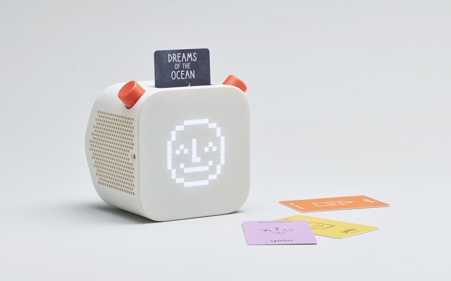
The Yoto Player super low res screen and cartridges :
From https://www.peterzimon.com/hog/ :
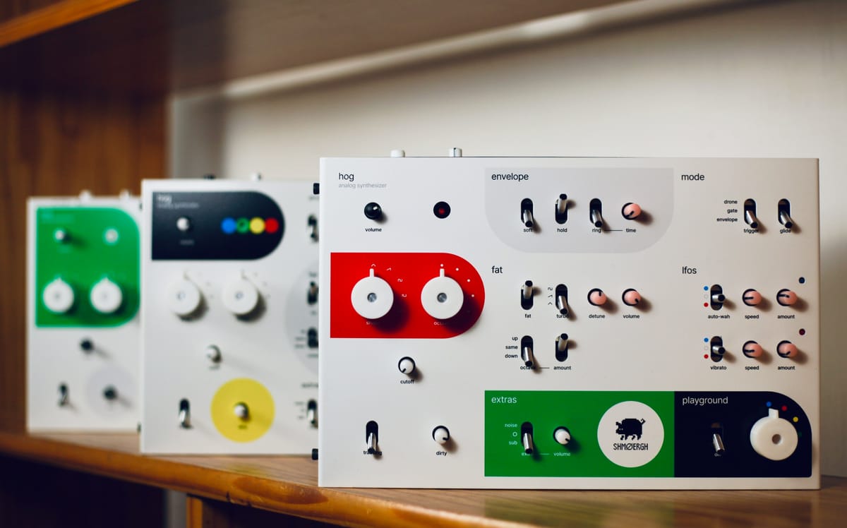
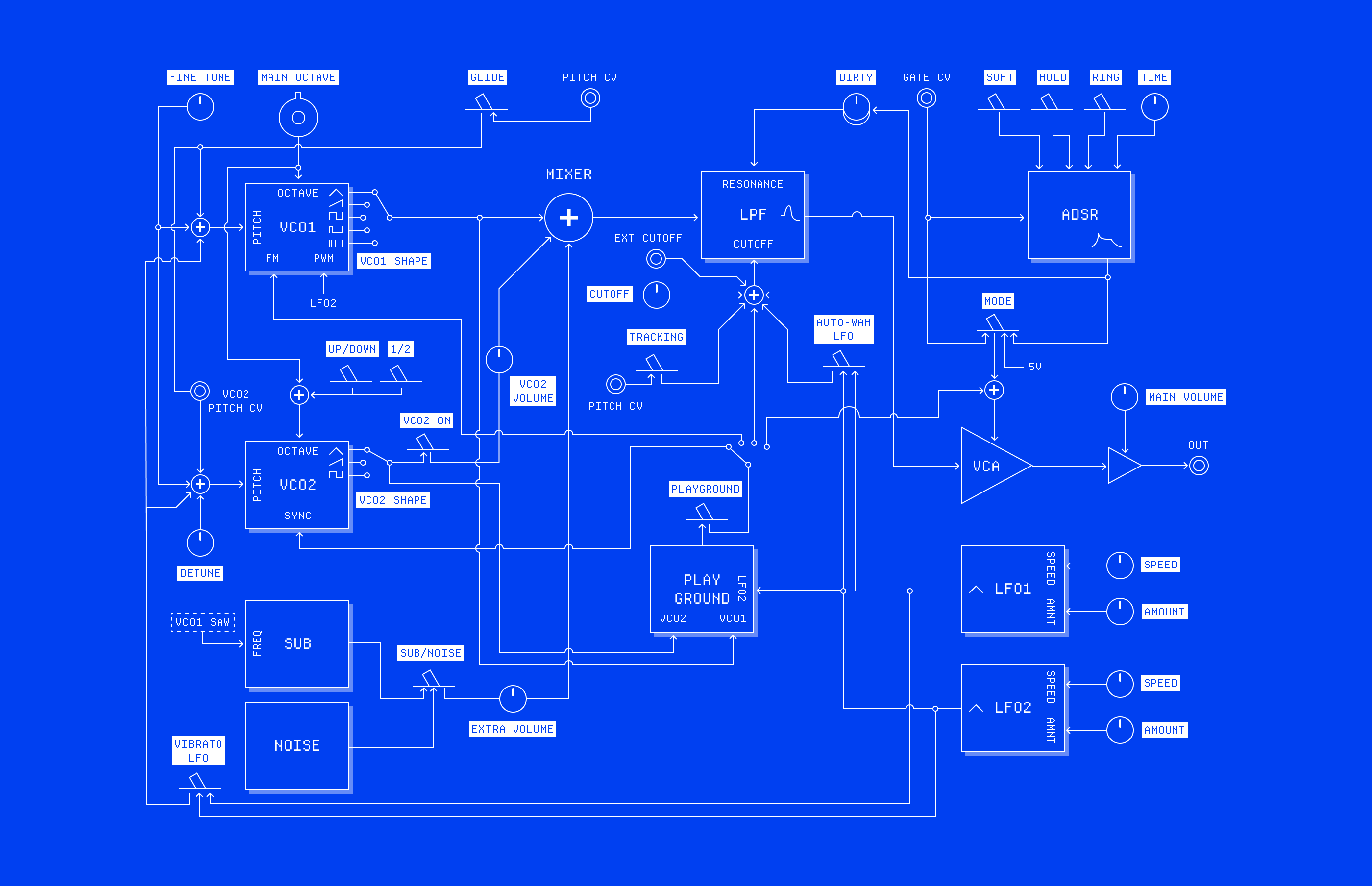
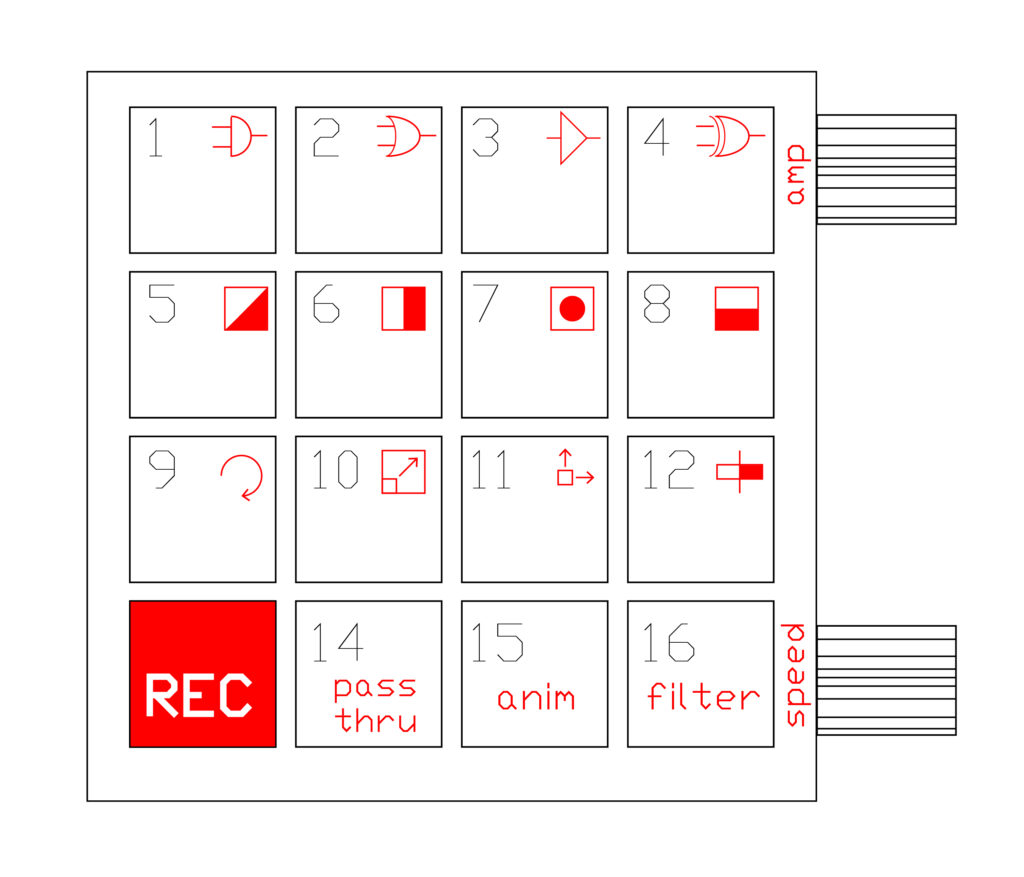
Here’s my attempt at an interface for a 4×4 version :
Check out this great video about image processing in P5.js :
****
I’ve been trying to develop a simple, tangible AI workshop for designers / artists but so far it looks impossible to do in the way that I want.
The huggingface series is nice, not too technical. The machine vision series has some good background.
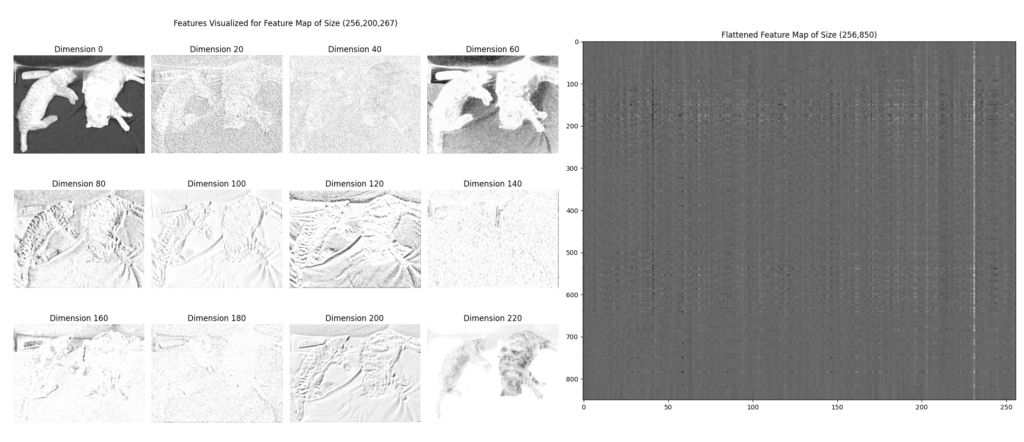
********
A great video from Coding Train on Convolutional Neural Nets https://www.youtube.com/watch?v=pRWq_mtuppU
The code is here : https://editor.p5js.org/codingtrain/sketches/GMRfsK7Wn
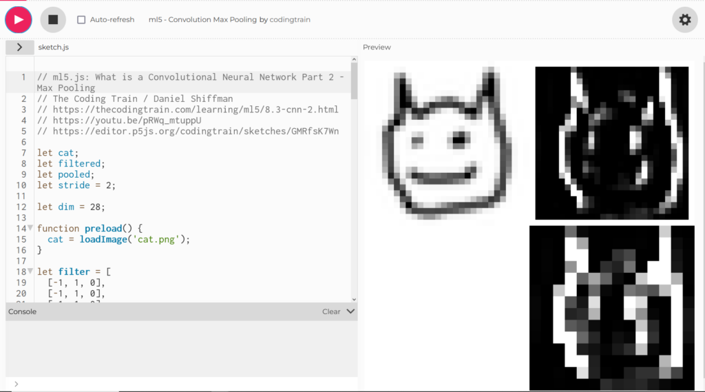
and also here for Perceptrons : https://www.youtube.com/watch?v=ntKn5TPHHAk
And this is a great article explaining the same concepts : https://ujjwalkarn.me/2016/08/11/intuitive-explanation-convnets/
Basically, take an input image of the correct size, then apply a series of random filters to it. Now use max pooling to further reduce the images and highlight the “features” that they depict. After doing this several times, you end up with a set of features. These are then connected to a perceptron which gets trained to associate different weights to the various features to classify the input image.
Here is another great series of articles explaining ML to artists : https://ml4a.github.io/ml4a/how_neural_networks_are_trained/
********
Kits for art/design + tech workshops / open source projects I could make :
Take project I’ve done / not completed and turn it into a kit ?
**********
Going to pitch this walking/crawling/climbing kit based on a dual shaft mini gearmotor based on this design (https://www.youtube.com/watch?v=ITJvy-HNXKY&t=522s) :
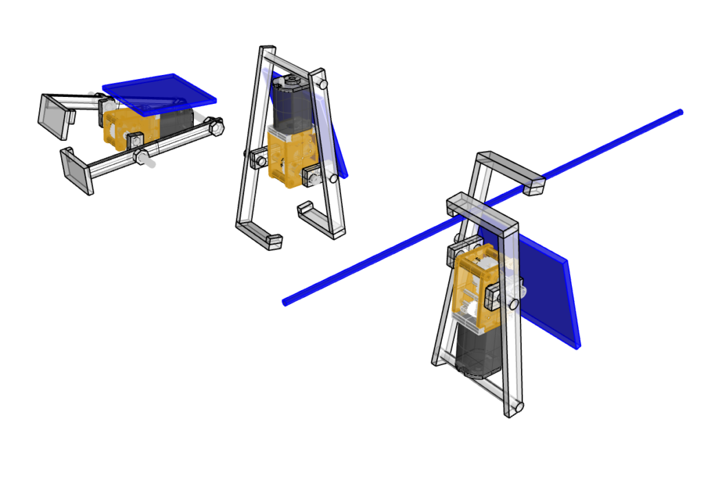
I received the dual shaft motors, they are really pretty (https://thepihut.com/products/dual-shaft-micro-metal-gearmotor). They turn on at between 1.5-2V which is good news, though we’ll have to see about the torque.
Now starting to think about how I could actually assemble this. I’m thinking to have lots of holes regularly spaced to give options for different ratios. I don’t know if they are bolts with nuts or rods. They would be 3D printed, transparent resin would be super cool, but for the kids’ workshop in nice primary colours. I think it would use the thin solar panels, one on each side (?), and connecting to the motor on the bottom.
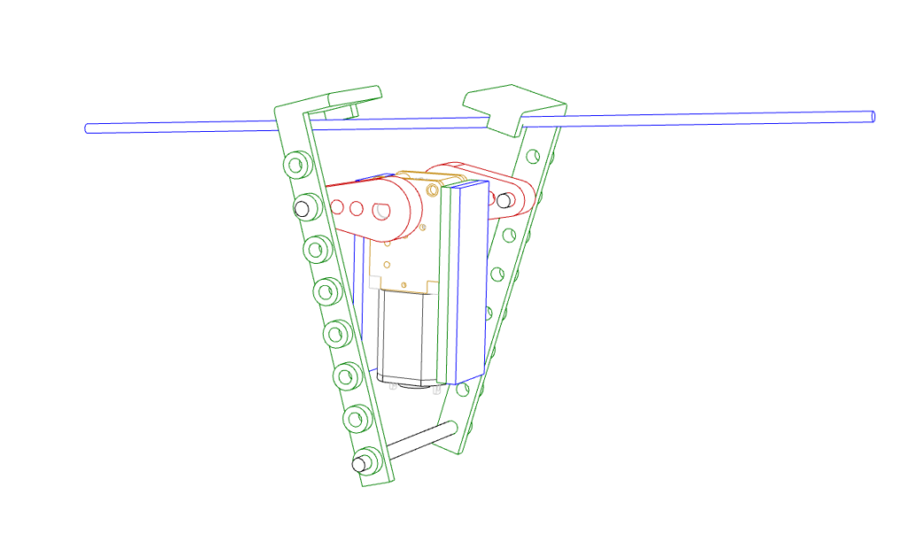
Here is the V.1

I didn’t realize that the bar at the bottom needs to be attached to the motor, and that the legs/arms have to slide around it. The arms also need to be longer.
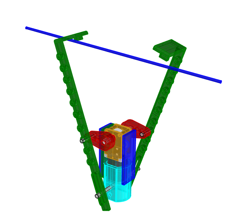
All the holes are too tight, the arms aren’t rigid enough, and I need a new shape for the hands.
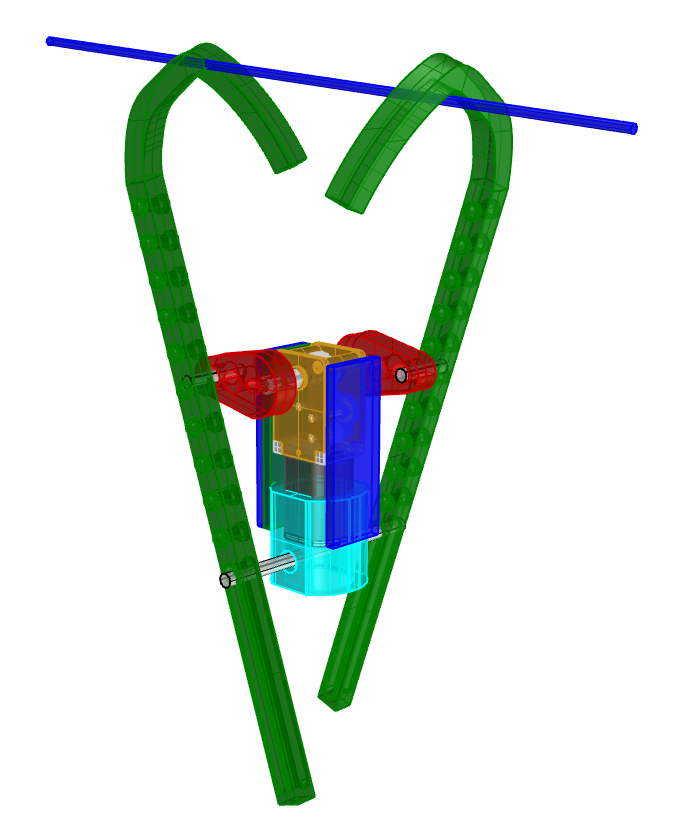
I’ve got a new idea, basically just to make the workshop about evolution and to let the kids make the kit and bend the arms differently.
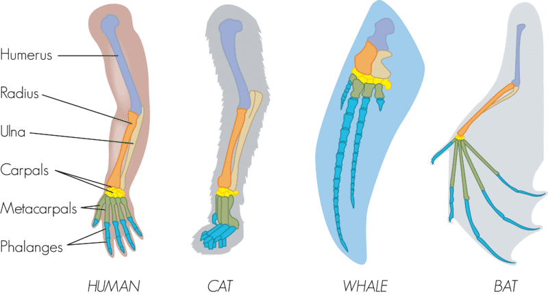
(https://sanibelseaschool.org/blog/2020/06/24/homology-and-analogy-a-lesson-in-biology/)

I remember last time doing this workshop with the optimized voltage supervisor ISL88001IE29Z and the efficient DMC2700UDM MOSFETs that I ordered from Digikey, that only half the circuits worked. I think it was because of the 2.9V versus 4.6 voltage supervisors that I ordered, but I’m not sure. I put a red mark on the circuits so it must be either the MOSFET, the supervisor, or the diode ? The new board will need to be tiny to fit on the motor so perhaps this workshop is less about soldering and more about mechanical movement.
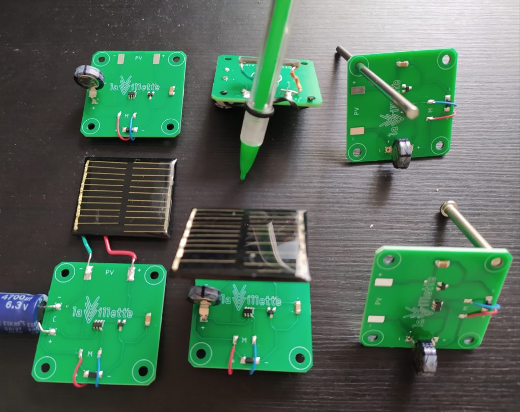
Because of the friction with the rope climbing robot, I don’t see this being an easy thing to make function reliably. I think it would be smarter to make a kind of ground crawling robot. The coolest would be to attach bendy wire to the two arms and let them form their own arms.
**************
Curious thing but I am coming back to the desire to make a video synth project. But it would have to be environmentally non-horrible. The only way I can see to do this is with aluminium substrate (100% recyclable) and making a one-sided board, and using recycled e-waste keyboards. I could edit the footprints of the mechanical keys so that the plastic parts go through the board but that the connections stay on the top side (aluminium on the bottom). The complexity of the board would need to be limited to not require any vias. No through hole components so either SMD VGA or just SMD HDMI. Then there is the difficulty of soldering with a giant heat sink underneath, I might need to use the oven or get it assembled elsewhere. The keys are the big challenge as they don’t come in SMD. One solution would be to modify the footprint to drill a hole near the connections so that I can manually wire them without danger that they short.
I would need to also replace the USB C connector to a fully SMD version.
Or maybe I do it in flexible, seeing as I haven’t tried that yet, and then add a lasercut or 3D printed stiffener to hold the keys in place. This way I don’t have the challenges of heat dissipation or the one-sided circuit board constraint. But then I have new issues : the connectors won’t be stiffly in place so any plugging won’t be possible. Stainless steel (100% recyclable) can be used as a stiffener but it is thin 0.1mm.
Rogers and Teflon substrates are toxic and not recyclable.
*********************************
I feel a tension when learning about electronics engineering as a designer : the engineering is telling me to continue to learn about more and more complex systems (I’ve wanted to go towards optics and high frequency boards, for instance), and yet these have no interest from a design perspective.
************
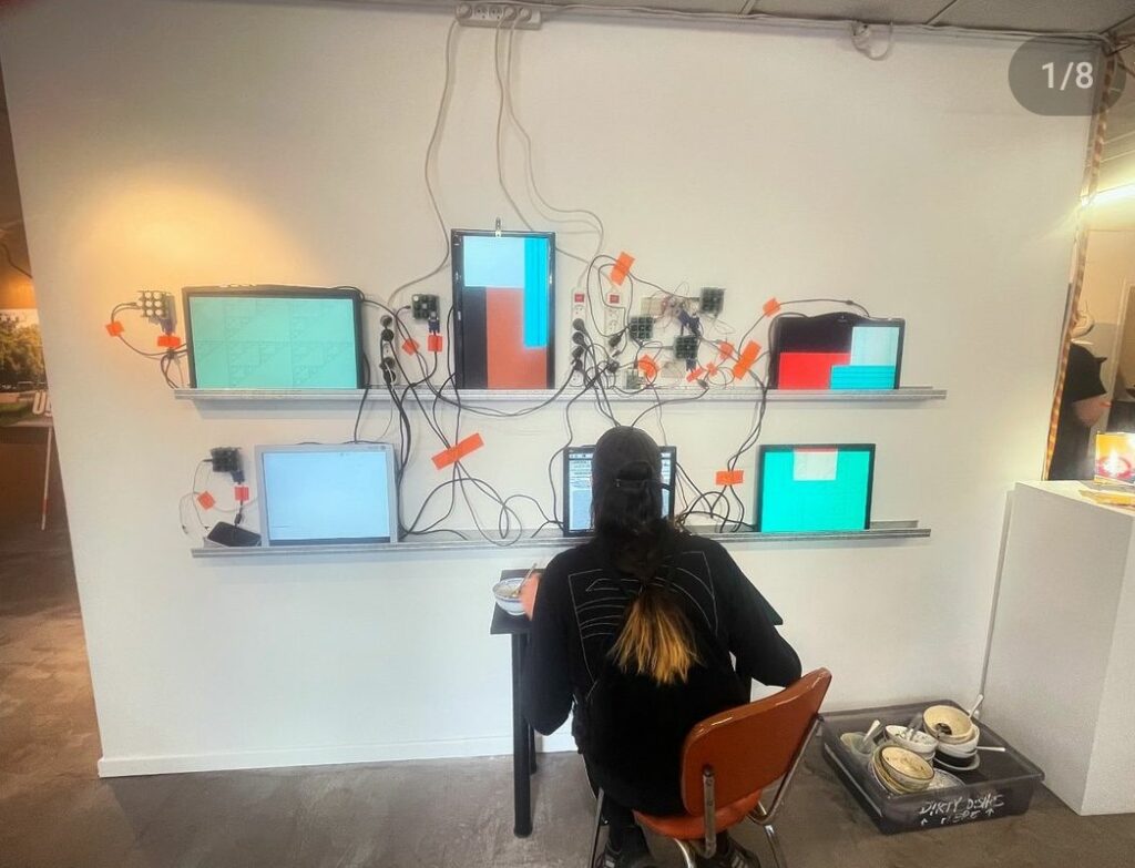
Just started the DSAA video workshop, here are my notes :
- If there was ever a time I actually needed to make a board for a workshop it is now!! The students really struggled to plug in cables between the VGA cables and to use the breadboard. A board that plugs into a breadboard, has a VGA IN and VGA OUT connections, bias pots connected to tons of amps, has multiple video signals ready to go, and has signals super clearly identified would have been a godsend.
- The worst was taking video from the HDMI>VGA converters. Their laptops were annoying, turning off the video stream at the slightest connection issue. A good solution would have been to provide them each with a rpi so they could loop their videos and turn on the forcing option where the rpi sends the video no matter what.
- It became clear also that this was a very experimental workshop, it’s hard to even find many examples of people using hardware to reinterpret video in general, it’s super niche.
- Unlike the NO SCHOOL workshop, these students didn’t have a particular tech interest or patience for debugging annoying things. Also unlike that workshop, I didn’t give them all boards which output animations.
- One cool thing was bytebeats (https://bytebeat.demozoo.org/), which saved me on the first day. They enjoyed making Arduino animations and the idea that an equation could make sound. I forgot how to add the element of time to the VGAX pattern example but on day 2 they were able to code animations.
- Of course it’s hard to mix Arduino generated images with images from a laptop so this was also kind of disappointing when they were able to combine two video signals. Ideally I would have already done the work to pave the way for easy and cool discoveries. If I had an rpi outputing their video at super low resolution for instance, this would have been possible.
- In the end I basically needed to go around to each group to plug in things myself and give them a personal demo. However, I forgot how experimental this whole process is. There is a lot of work to get a very limited and ephemeral result (especially how often things need a bias pot and amp before and after being input to another module). I could, however, show them how to amplify, delay with a coil of wire, attenuate with a potentiometer, turn on/off a channel with a pushbutton, and we did manage one XOR circuit. We haven’t yet mixed two images, mainly because it’s hard to get two laptops to output video when they are not sending the H and V signals. The comparator I brought didn’t seem to work well, and because we didn’t have two videos really the XOR was underwhelming.
- I did like the references I brought to the class though, which I felt were very open-ended and varied in time and genre touching on video games, scientific and military use of video, machine vision, avant garde video, contemporary work and photography. They also seemed to like my work posted on instagram. But I needed to be able to help them make equally cool stuff and haven’t yet.
- I kind of remembered that all the references I am talking about share that they use a representation technology to give form to the medium itself instead of the message passing through it. I.E. they are all “meta” projects.
- Some new discoveries thanks to Boris like Eric Rondepierre, and two apps for storytelling : twinery.org and gbstudio.dev.
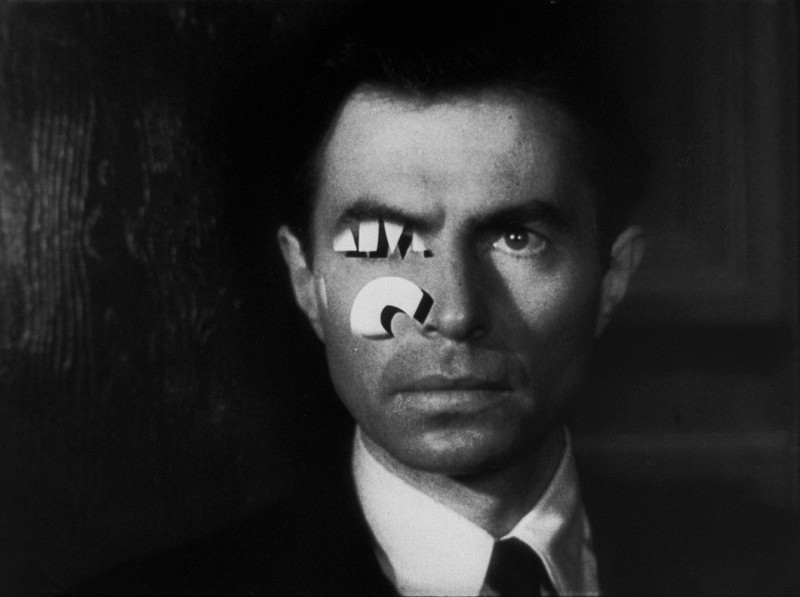
Eric Rondepierre taking a photo at the exact moment the text overlay enters the screen over a face.
***
Part deux of this workshop went much better !

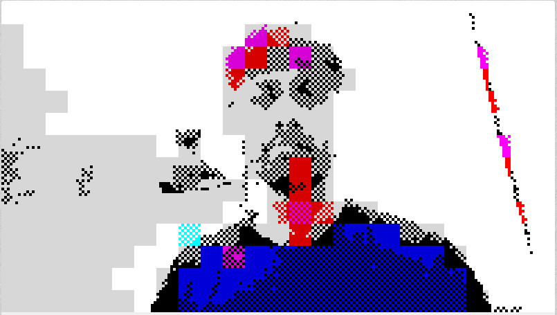
I asked the students to take two stills from the scene that they picked, and convert them into a 120×60 pixel bitmap image using the VGAX 2bitImage tool. (Still needed Notepad++ afterwards to remove the curly brackets and trailing commas; I should also learn how to include the second bit for next time). Then they inserted their images into the VGAX>Image code and changed the time delays. I like the idea that two images at this super low resolution represent the minimum to constitute a “scene” or an animation. I then showed them how to make black and white, which led to the discovery by the students of all the different color possibilities when using slightly different values of resistor.
When they were down-sampling their images and modifying the array of values, there was an opportunity to talk about pareidolia and show them this image to show how little information is necessary to convey an iconic image and how those values are represented in the computer with numbers :
![]()
One thing that would have been great would be to have played with the images in the code, like slowly degrading them with random pixels etc. I couldn’t figure out how to do this fast enough in class so I dropped the idea. I also need to learn to have photoshop output two color pixels not just one.
The challenge for the students was to make some kind of hardware manipulation that made sense considering the scene they chose. Boris the teacher set it up so that this framing took place after the experimentation, allowing the students to make chance discoveries.
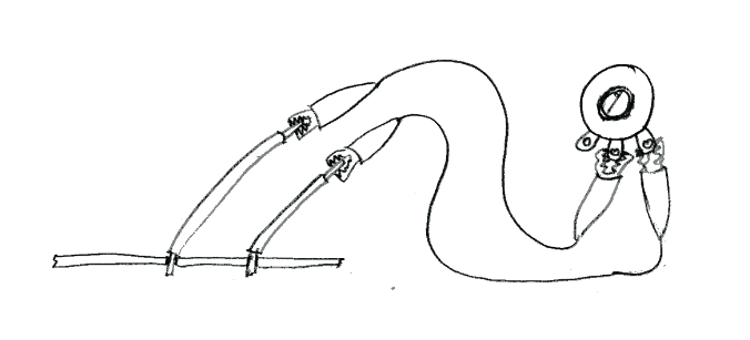
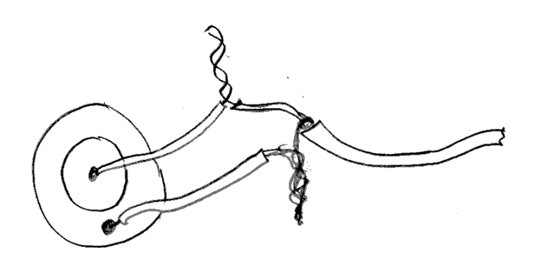
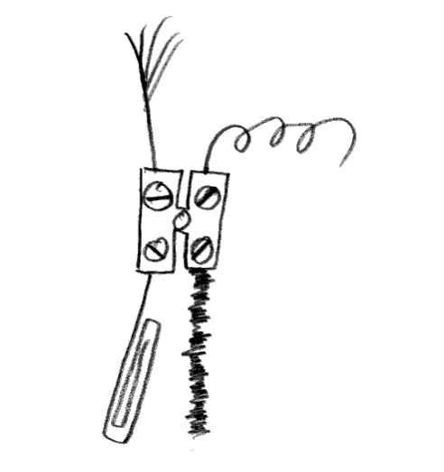
Some cool things they came up with :
- the op amp was a big success, with floating input, plugged in to the adjacent row in the breadboard (to create a capacitor) or connected to a piece of aluminium foil.
- Using one Arduino to output video on two screens !
- Taking screens off their stands, changing the angle that you look at the screen to see different colors appearing/disappearing.
Things I tried :
- Unfortunately sending two Arduino images from two different Arduino rarely lines up closely at all, I guess the clocks are not that accurate ? This works with FPGAs well though.
- Inserting our own images into the HighRes code didn’t work however.
- I tried an HDMI splitter which I think did help keep video from the computer being sent no matter what. The VGA splitter and multipliers I tried didn’t appear to work.
- I needed to try a bunch of different monitors to find (old) ones that accepted the resolution of the VGAX. Thankfully we had a ton available to chose from.
- At some point I showed them how to plug things in in a reliable manner on the breadboard and they understood and made more solid circuits.
- I didn’t get around to testing the TVOUT and CRT monitor with Arduino, but it would have been a whole other can of worms.


*****
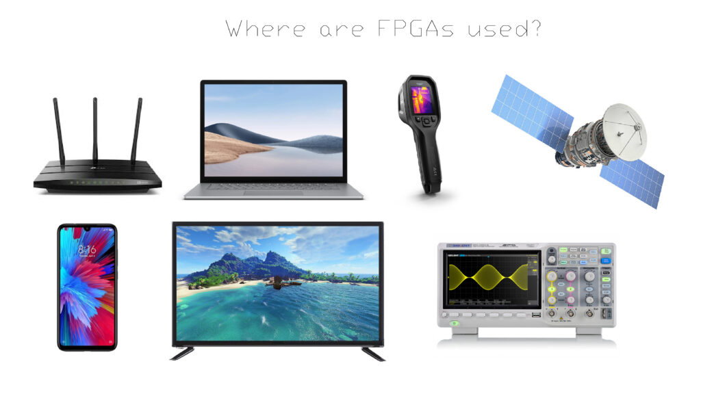
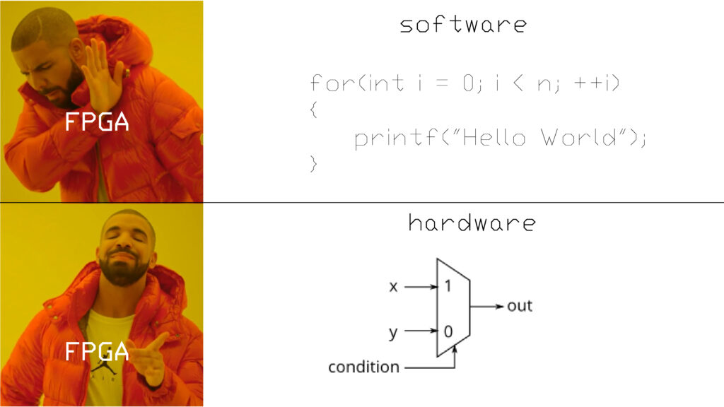
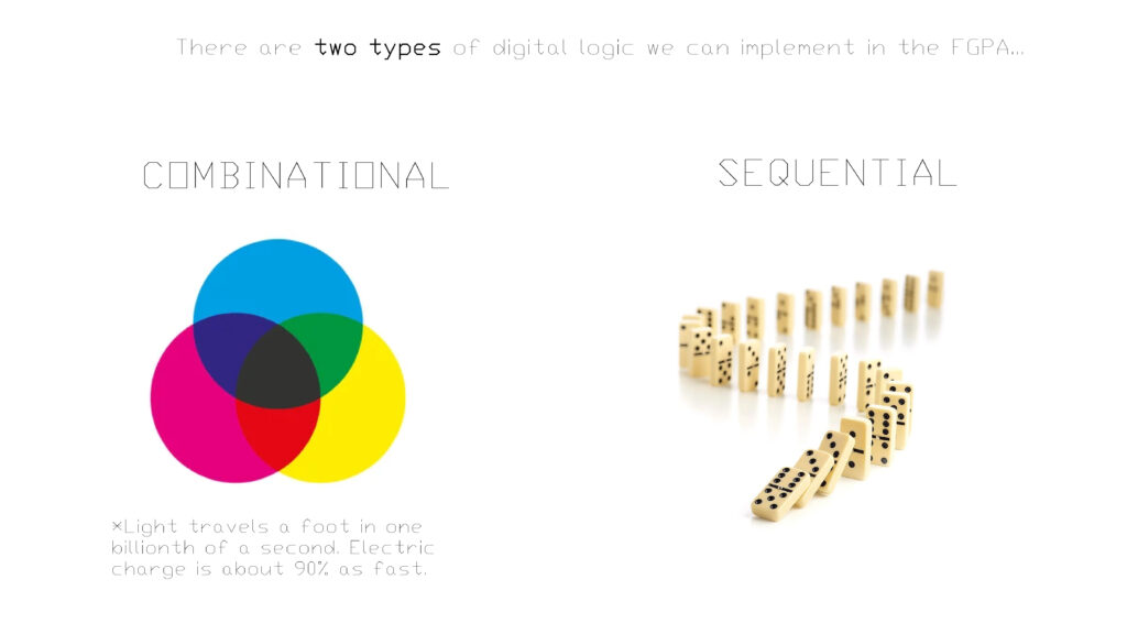
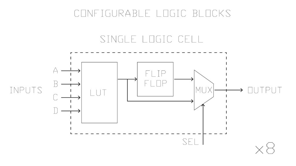
Preparing the FPGA workshop at the IFT. Hoping to be able to go further in depth with FPGA and experimental video ! Some sample slides :
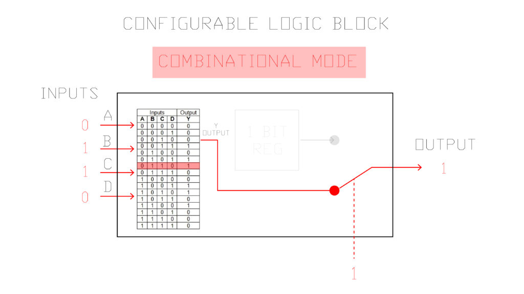
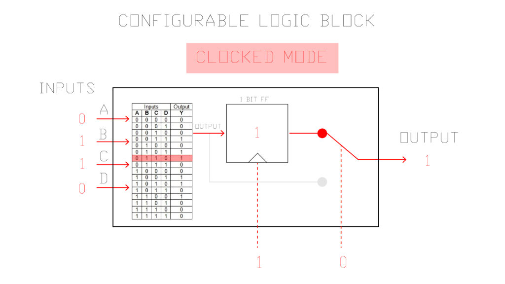
Some thoughts from giving this workshop at ESILV from DAY 1:
- It is not Mac friendly ! Some had USB driver issues. I should prepare for next time the driver solution. Getting everyone in groups helped though because things worked at least on one person’s machine.
- We ended up doing day 1 and 2 on the first day. It’s too much to ask them to do HDL bits exercises for a whole day, they want to get their hands on the hardware !
- It’s too hard for them to follow everything on my screen, especially because it’s so technical (especially for Diamond Programmer), they need to have access to the same PDF.
- The marble “Y” latch is useful to take about flip flops and how they “remember”. I also found myself playing that wooden binary counting video several times to illustrate frequency division with counting.
- They need to download Diamond Programmer separately from IceCube2.
- I didn’t give them the tools they needed to do the blink themselves (They didn’t get to the always blocks in HDL bits). I should have told them about how registers automatically roll over, how to increment, etc.
- There MUST be a better way to add a verilog file into IceCube2 that doesn’t yet exist !!
- The pin constraints edits I did using the pin constraints tool weren’t saved on various people’s machines. You need to select LOCKED and save before resynthesizing.
- It would have been cool to do a demo of my FPGA video board right at the beginning.
ESILV from DAY 2:
- Started the day with asking them to change the LED based on input. Told them to work and document in groups.
- It would be useful to have some demo codes prepared for them (gradient, simple shape, example animations) so they don’t have to do absolutely everything from scratch.
- I should show them how to add a module to their code like the trig function module
- I don’t currently have a slide talking about the open-source FPGA synthesis alternatives
- Remind them that when they take the code from Alhambra II git repo that they need to change the clock to pin 21 on the IceStick ! Also, some people needed to add a reset to a pin and pull that to ground to get their code working. Also, several people had issues with the pin constraints editor, it helped to lock and save it before Running All in IceCube2.
- Show them the Secret Life of Machines Fax + CRT screen videos.
- Show them a R2R Ladder DAC so they know how to add more bits to the colors.
- The VGA pinout is female instead of male, and I shouldn’t show the resistors if I want them to skip this.
- Several groups needed an oscilloscope to see the signals and make sure they were correct, they also needed to try a few screens until they got one working.
- I told them that v_count increments once per frame but it increments once per line !
- They all wanted to use division, trig functions, and other things not supported by verilog…I need to warn them in advance.
ESILV from DAY 3:
- brought in the VGA recorder which was allowed us to do some recordings.
- brought an HDMI to VGA converter so they could start getting video from their laptops and passing it through the FPGA
- Fabien came in and did a presentation of Migen and IceStorm, it is about 1000 times faster than synthesis and routing in the IceCube software. He also demonstrated loading an entire custom architecture computer onto the UP5K, though I don’t totally understand yet how you “use” that computer really?
- I showed them companies that make video synths and asked them to design an interface for their synth.
- They made circles (by calculating the distance from the pixel being drawn using Pythagore, making sure not to make any negative numbers, and setting a threshold) and squares that animated, tried to make triangles. There were some gradients. They were less interested in byte beats but wanted to take video in and make framebuffers.
- I showed them the tertiary operator but I don’t think anyone used it. I should have given them a bunch of example verilog codes on a dropbox to tweak.
- I didn’t end up talking to them about race conditions, latches or meta stability.
- h_count is just the columns and v_count is just the rows.
- Could add a section about how FPGAs are being used for research (ask Fabien)
- I should get a video pass thru set up with rpi and show them how to XOR different color channels.
- Going from a 1D index to 2D index formula => h_count + (v_count * h_width); Explained here : https://softwareengineering.stackexchange.com/questions/212808/treating-a-1d-data-structure-as-2d-grid
*********
Fabien just sent me this awesome verilog VGA simulator !! https://vga-playground.com/
Worth looking at the various codes to see how the effect is produced (especially the balls code).
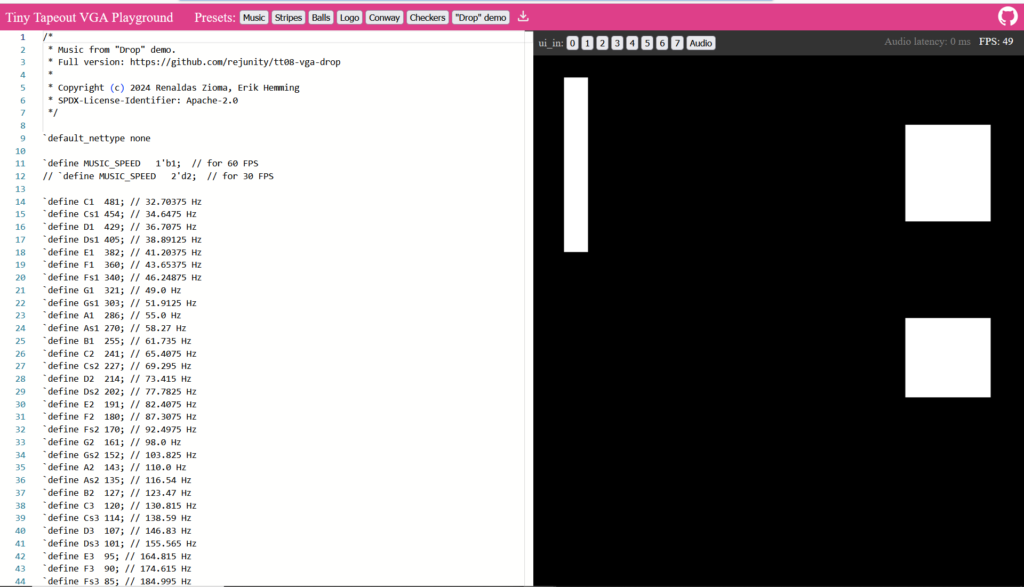
Check out these other verilog resources that are even better :
https://8bitworkshop.com/v3.9.0/?platform=verilog-vga&file=test_hvsync.v
The video examples are super helpful !
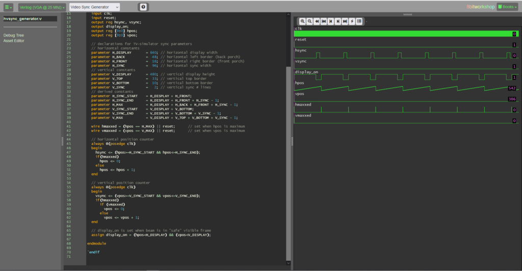

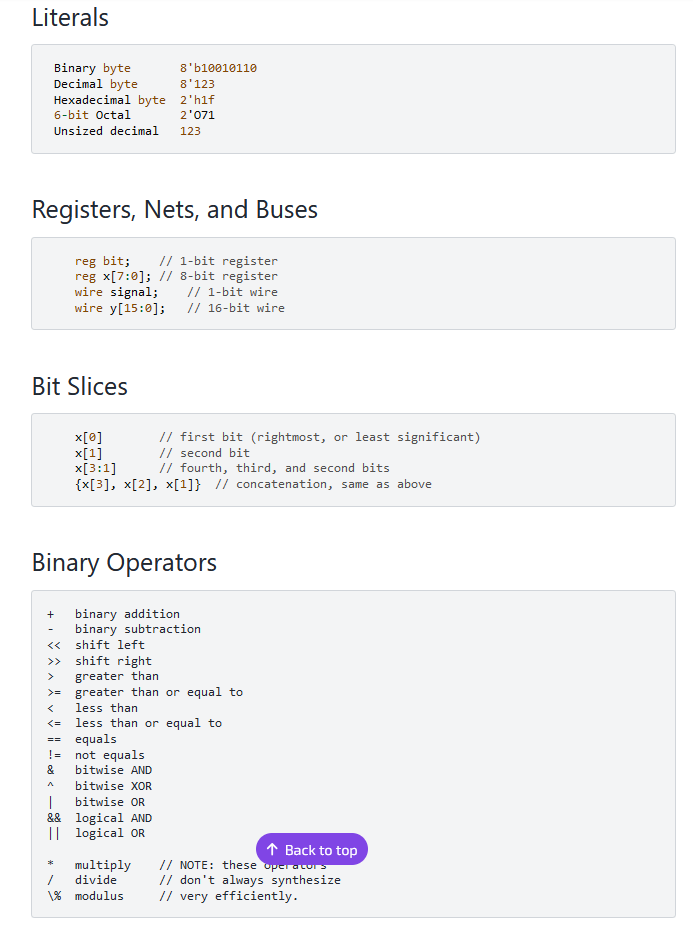
A nice verilog cheat sheet I wish I had known about for the class ! :
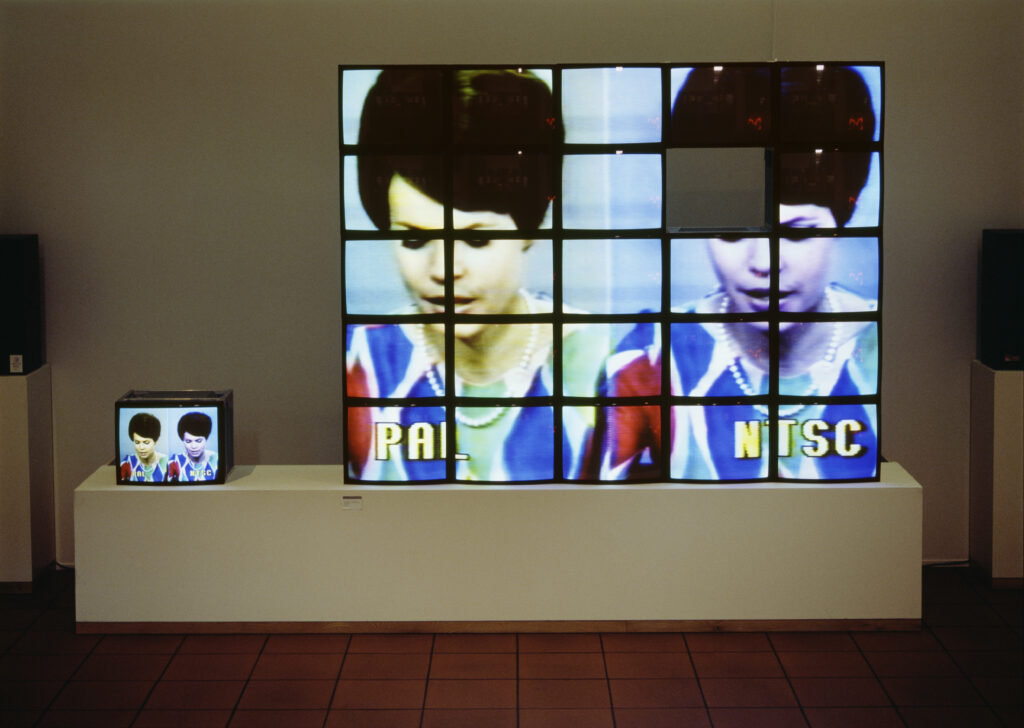
From an MIT expo about boxy monitor art before projectors :
Maria Vedder, PAL oder Never the Same Colour, 1988.
I am realizing that all this 2D animation just gets wrapped onto 3D things with shader (except for when they move vertices around!). Super nice shader tutorials, and wow the power of examples !! :
https://benpence.com/blog/post/psychedelic-graphics-0
Found a shader I liked on shadertoy :
*******************
I’ve proposed a Neural Net workshop to l’ENSCI :
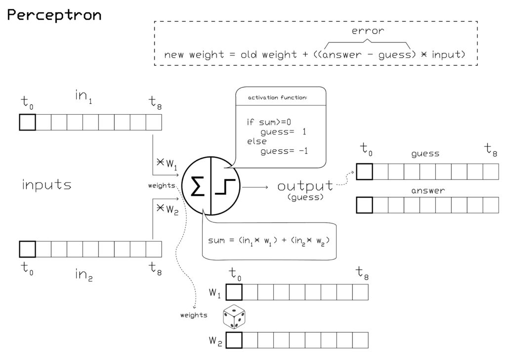
Here’s a simple 2 input 2 output (no middle layer) “neural network” .
1. I think it would be cool to use the similar system for the handwritten digits classification, without a middle layer. (The challenge for me seems to be iterating over a bunch of images with labels in processing. )
2. After this, I want to make a very simple tiny neural net and add a middle layer but avoid the math and just randomly choose different weights, evaluate the total mean loss, store the weights, and repeat for X number of times, eventually taking the best weights. This would be a good introduction to how complex backprop gets very quickly.
3. I’d then like to do some convolution and pooling, but keeping with this very simple, impractical and inefficient design. This is so visually useful to understand how machine vision works.
*****
I have been trying to understand reverse propagation but now I think I should do a series of easier algorithms like from the AI class at MIT : K nearest neighbours, search, etc.
Current plan developed with Mariana is to do a warm up with Teachable Machines, then do a Processing intro, two toy AIs : search and perceptron, and then to end on the ML5 library and some examples of artists using AI.
********
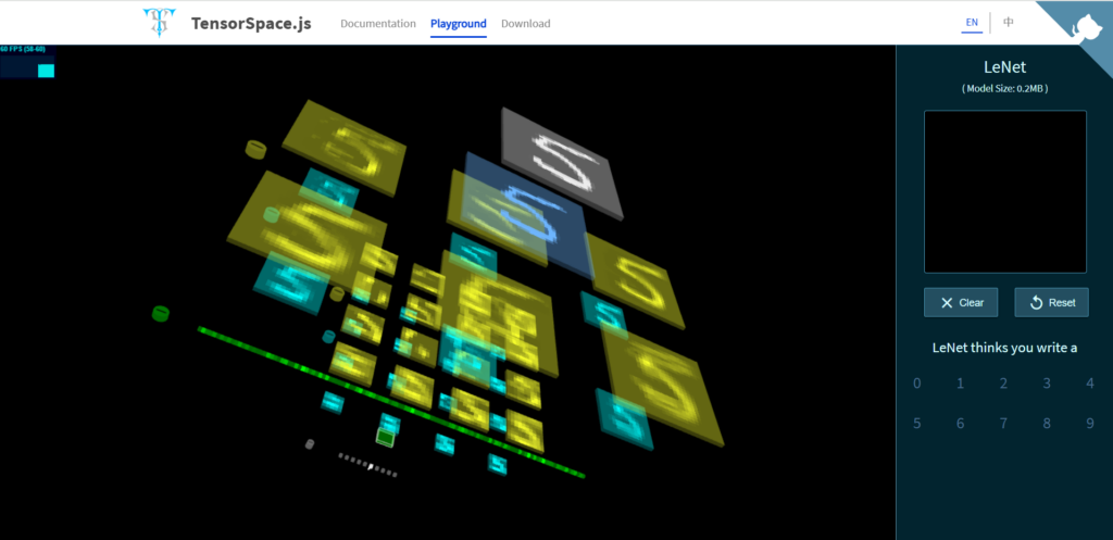
Finally did the AI class, it had since transformed into a class about Le Net from 1998 teaching the students to work through examples of a perceptron and basic convolution. Thankfully I had Mariana’s help, she brought a great Teachable Machines Exercise and introduced the students to ML5 at the end in order to make the worst volume control or phone number entering UI imaginable (in this style: uxdesign.cc/the-worst-volume-control-ui-in-the-world-60713dc86950). I also got them to learn p5js and put their example codes to share in an excel file.
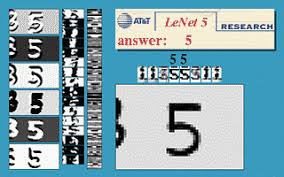
This tensorspace visualization of the various layers of convolution, pooling, and eventually neuron layers :
If I were to redo this workshop, here are some changes I would make :
- I think I would have used this site more for demo purposes https://tensorspace.org/html/playground/lenet.html
- I need to know the material better, and practice more before hand. There were tons of imprecisions in my language and understanding. Little things like, the weights in the paper exercise probably should have been initialized between -10 and 10, for example.
- I don’t know why the convolution doesn’t average the sum in the end. I also don’t understand the values, why am I multiplying by such small numbers when I want levels of grey in the end. Is there a ceiling function at some point that constrains the output ? I would prefer do to this with 0-255 so that everything is 8 bit. I like this gif to explain the working though : miro.medium.com/v2/resize:fit:1052/1*ZCjPUFrB6eHPRi4eyP6aaA.gif
- What is precisely the difference between a neuron and a perceptron ?
- A student Thomas had the idea to get different groups training differently, some on more data, etc, so that at the end we can compare the results and learn about the different parameters that effect training.
- Forgot to talk about the activation function, also had a question about whether a single neural net could use diff activation functions and I didn’t know the answer.
- I didn’t do a great job explaining how multi layer neural nets can begin to see features, even though I took some good diagrams from the ml4a site.
- Because these are engineering students, I should explain that we are doing dot products.
- I don’t know how correct this was, but I improvised an metaphor about how in a large corporation that commits some environmental crime, it’s hard to know how much at fault each individual person is. Basically, it’s hard to attribute the percentage of total blame to a single weight in a multi-layer network because it’s unclear what their role was precisely in contributing to the wrong answer (this is where the science of back propagation comes in).
I enjoyed most the hands-on perceptron training. The majority trained their model and got 100% accuracy on the test set. Most had a bit of difficulty too, so it wasn’t super obvious and required the practice :
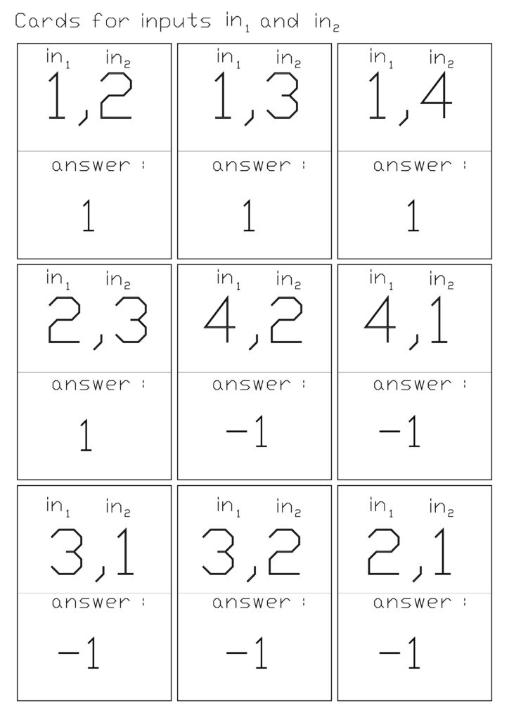
There were two decks, one for training and one for testing :
Here they had to use the transparency printed filters (next page) to transform the input image and put the resulting convolved image to the right :
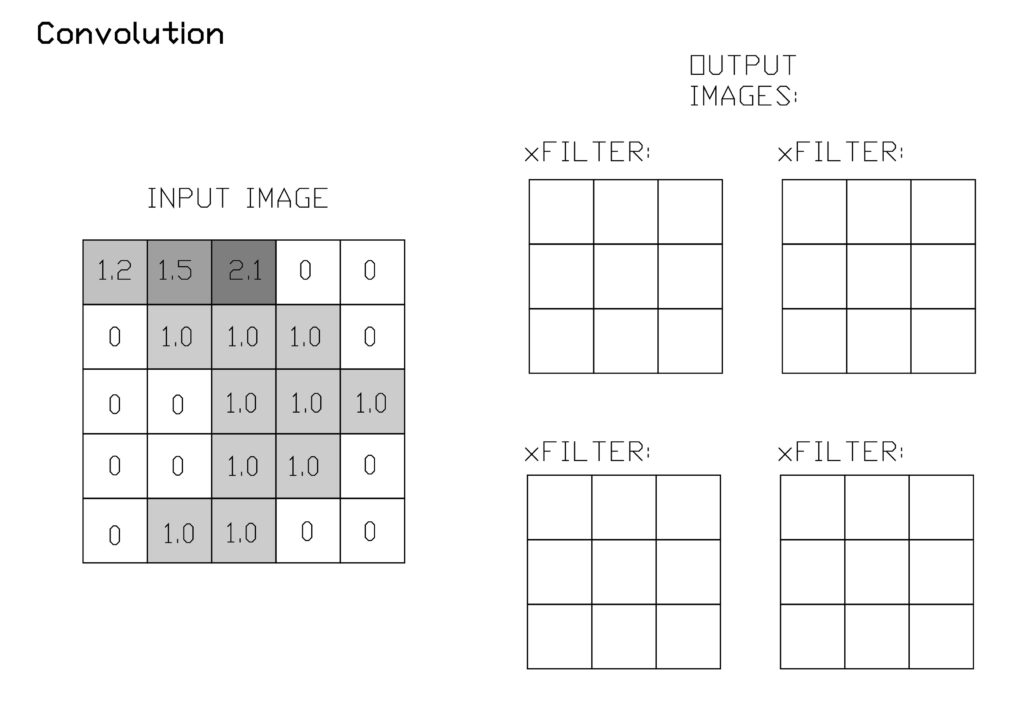
I think Identity should have been 0 all over except the center where it should have been 1 :
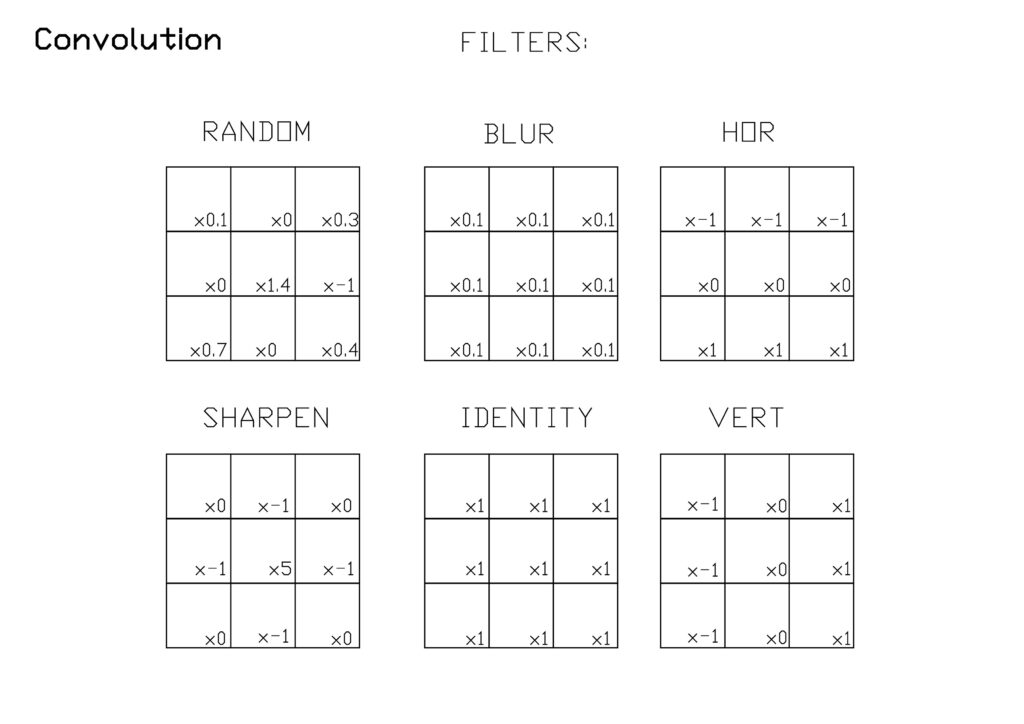
I gave them this p5.js code to complete :
// Convolution challenge
// take a 29x29 pixel black and white input image from the MNIST database
// output a filtered image
// implement the following filters : edge, blur, identity (no filter).

let input_image; // the input image to filter
let input_image_copy; // the input image to filter
let filtered_image;
let blank_image;

// convolution filters :

let vert_edge_filter = [

// COMPLETE THIS FILTER

];

let hor_edge_filter = [
[-1, -1, -1],
[0, 0, 0],
[1, 1, 1],
];


let identity_filter = [

// COMPLETE THIS FILTER

];

let blur_filter = [

// COMPLETE THIS FILTER

];

//select your filter here

let filter = blur_filter;

function preload() {

// P5js needs to preload images before they are used in the setup or draw sections
// you'll need to create a login, then create a folder called "assets", then place the image inside this folder and rename it as input_image

input_image = loadImage("/assets/input_image.jpg");
}

function setup() {

createCanvas(540, 540); // input MNIST images are 29x29 = 841
input_image_copy = make2Darray(input_image);
blank_image = makeBlankImage();
filtered_image = convolve(input_image_copy);
show(filtered_image);

}


function convolve(img) {

let convolve_copy = [];

convolve_copy = img; // make a copy of this (which we will overwrite with the filtered image)

// iterate through our image array and apply our 3x3 filter
// avoiding edge conditions

for (let x = 1; x < 30-1; x++) {
for (let y = 1; y < 30-1; y++) {
let a = convolve_copy[x][y]; // initialize the neighbouring pixels in a 3x3 grid
//
// COMPLETE THIS CODE
//

blank_image[x][y] = sum;
}
}
return blank_image;
}

function show(array) {
//draw the 28x28 input images or show the weights
for (let x = 0; x < 30; x += 1) {
for (let y = 0; y < 30; y += 1) {
fill(array[x][y]); // roughly map and constrain the weights to 0-255
stroke("white");
rect(x * 10, y * 10, 10, 10); // scale the pixels by 10 in x and y
}
}
}

function make2Darray(img) {

img.loadPixels(); // creates a 1D array for our image
let input_image = [];

// convert our 1D colour image into a 2D greyscale array called input_image with X and Y indices :
for (let x = 0; x < 30; x++) {
input_image[x] = []; // create nested array

for (let y = 0; y < 30; y++) {
input_image[x][y] = img.pixels[(x + y * img.width) * 4]; // there are 4 elements R,G,B, Alpha for each pixel
}
}
return input_image;
}


function makeBlankImage() {

let blank_image = [];

// convert our 1D colour image into a 2D greyscale array called input_image with X and Y indices :
for (let x = 0; x < 30; x++) {
blank_image[x] = []; // create nested array

for (let y = 0; y < 30; y++) {
blank_image[x][y] = 0; // there are 4 elements R,G,B, Alpha for each pixel
}
}
return blank_image;
}
One solution for the convolve function is here (several students did this instead with a pair of nested loops) :
function convolve(img) {

let convolve_copy = [];

convolve_copy = img; // make a copy of this (which we will overwrite with the filtered image)

// iterate through our image array and apply our 3x3 filter
// avoiding edge conditions

for (let x = 1; x < 30-1; x++) {
for (let y = 1; y < 30-1; y++) {

let a = convolve_copy[x][y]; // initialize the neighbouring pixels in a 3x3 grid
let b = convolve_copy[x][y + 1];
let c = convolve_copy[x][y - 1];
let d = convolve_copy[x - 1][y];
let e = convolve_copy[x - 1][y + 1];
let f = convolve_copy[x - 1][y - 1];
let g = convolve_copy[x + 1][y];
let h = convolve_copy[x + 1][y + 1];
let i = convolve_copy[x + 1][y - 1];

let sum =
a * filter[1][1] +
b * filter[1][2] +
c * filter[1][0] +
d * filter[0][1] +
e * filter[0][2] +
f * filter[0][0] +
g * filter[2][1] +
h * filter[2][2] +
i * filter[2][0];

blank_image[x][y] = sum;
}
}
return blank_image;
}https://editor.p5js.org/merlinmarrs/sketches/I9e6HC8_A
I tried and failed somehow at making a single pixel classifier that would just say if an input pixel was closer to dark or closer to light. I wonder if there is an issue taking only a single input for a neuron ?