Robot Light Painting
Autodesk OCTO Lab, Pier 9, San Francisco

Video credit: Charlie Nordstrom
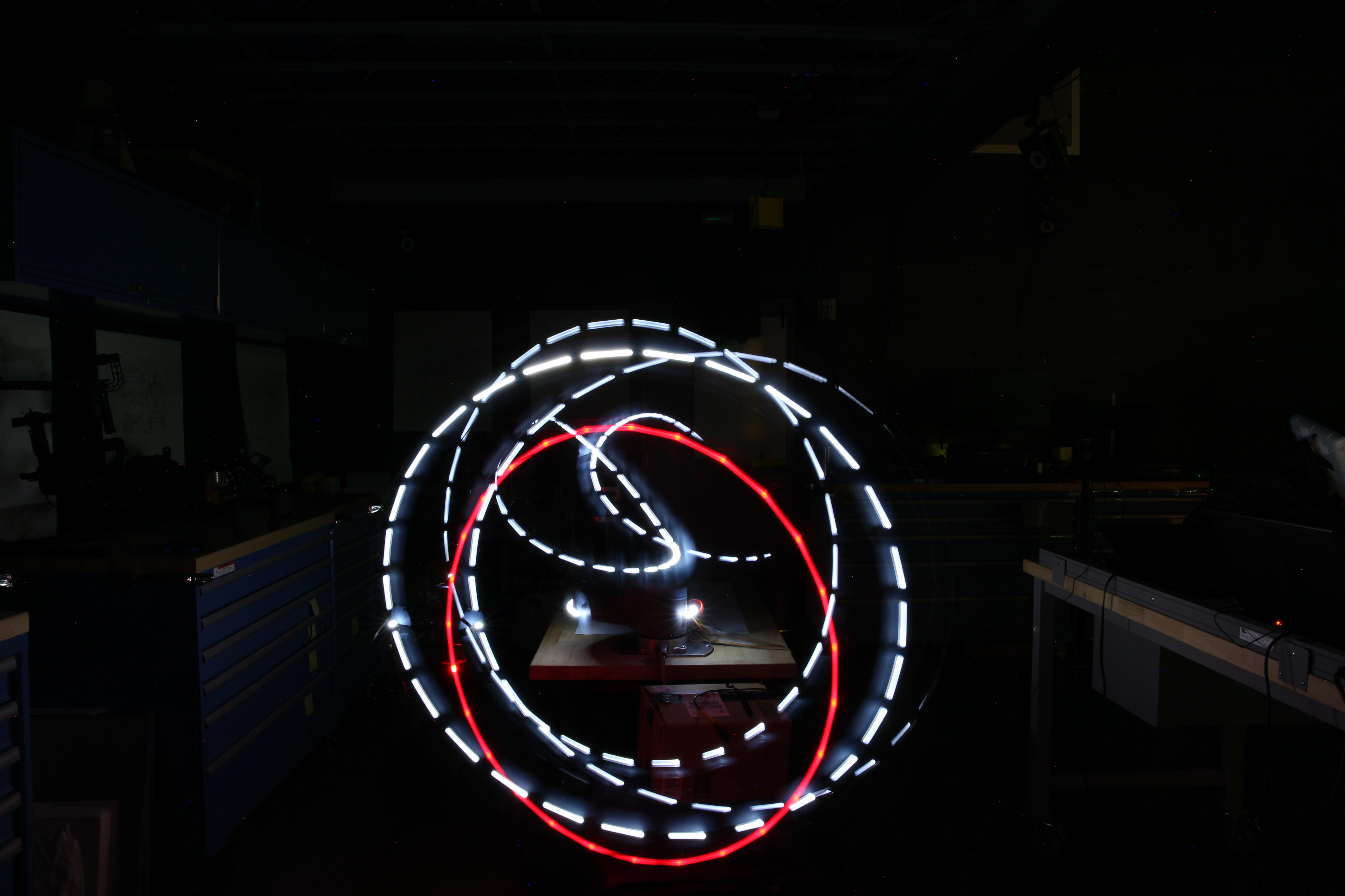
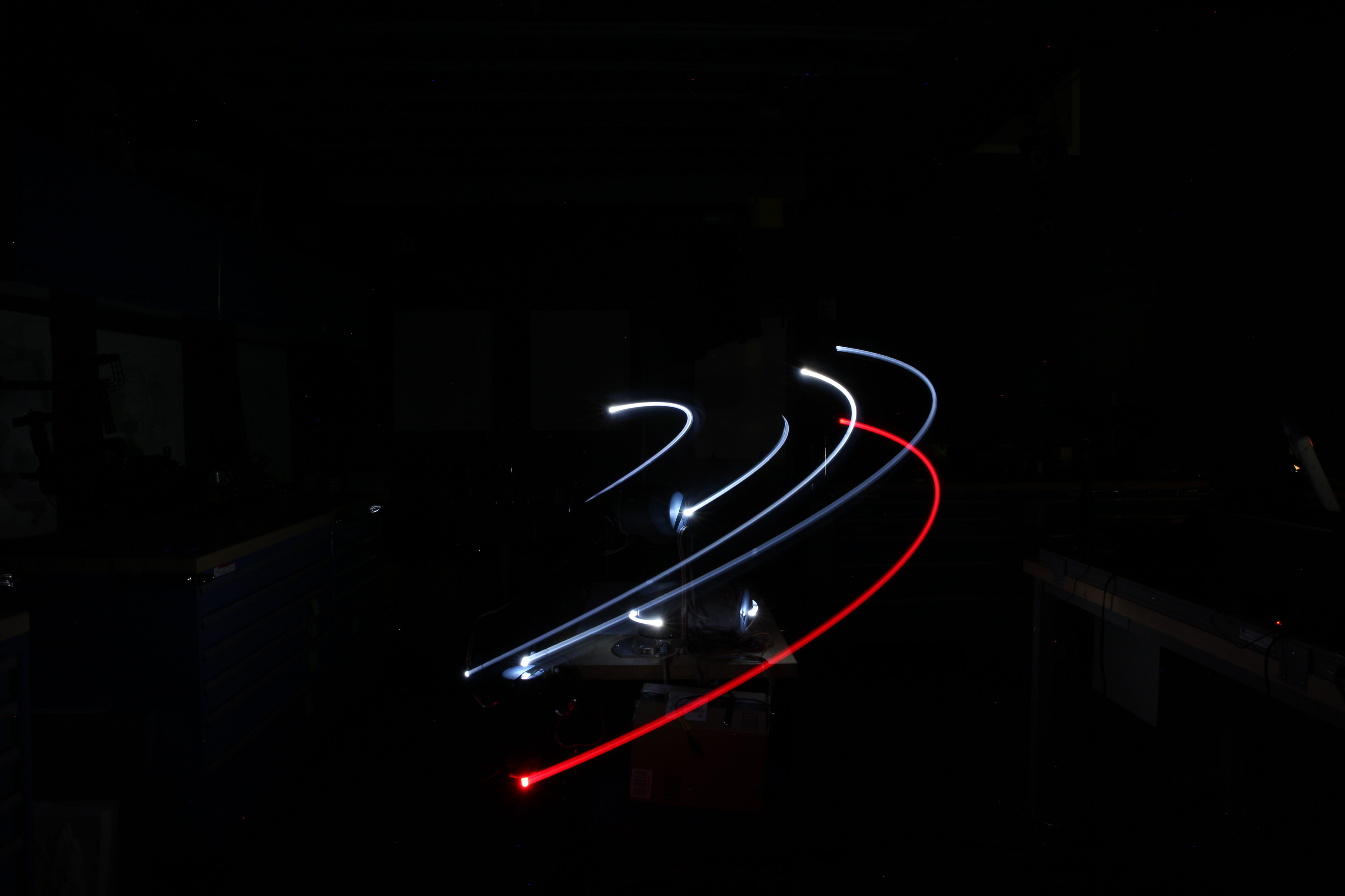
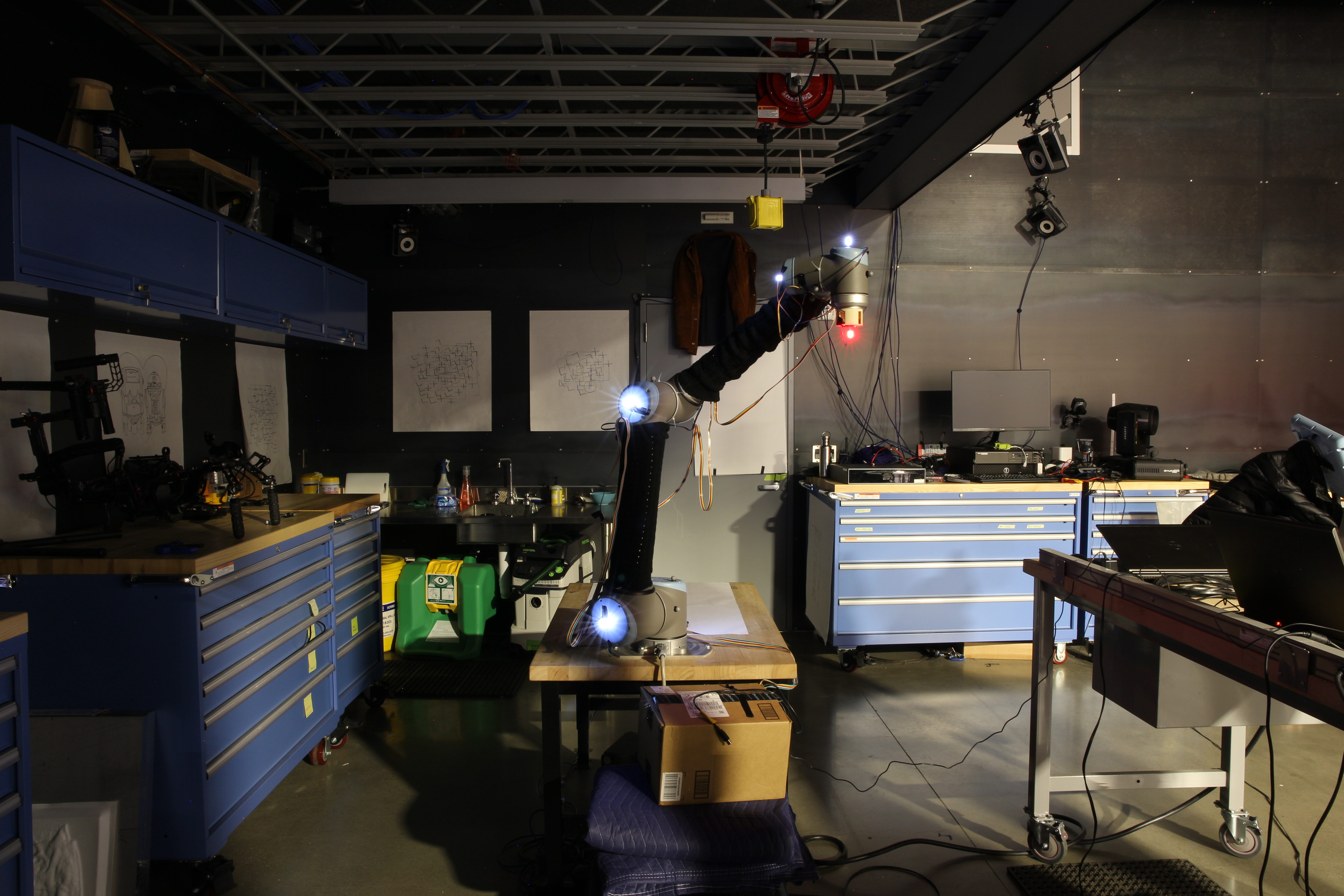
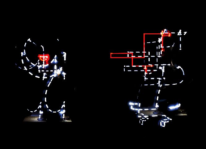 Two time lapse photographs of a Universal Robot Arm, white FLEDs are located on each joint (shoulder, elbow, wrist) and a red LED is located on the end effector. Joint Interpolation, on the left, and Linear Interpolation, on the right.
Architects typically a robot arm to move tools along paths, and the arm uses its inverse kinematic solver to achieve the necessary angles over time. However, if we were to move joints themselves, by so-called joint interpolation, we would discover resultant end-effector paths which relate to the way the robot arm is physically embodied. What kinds of forms could result from exploring the way a robot arm “wants” to move?
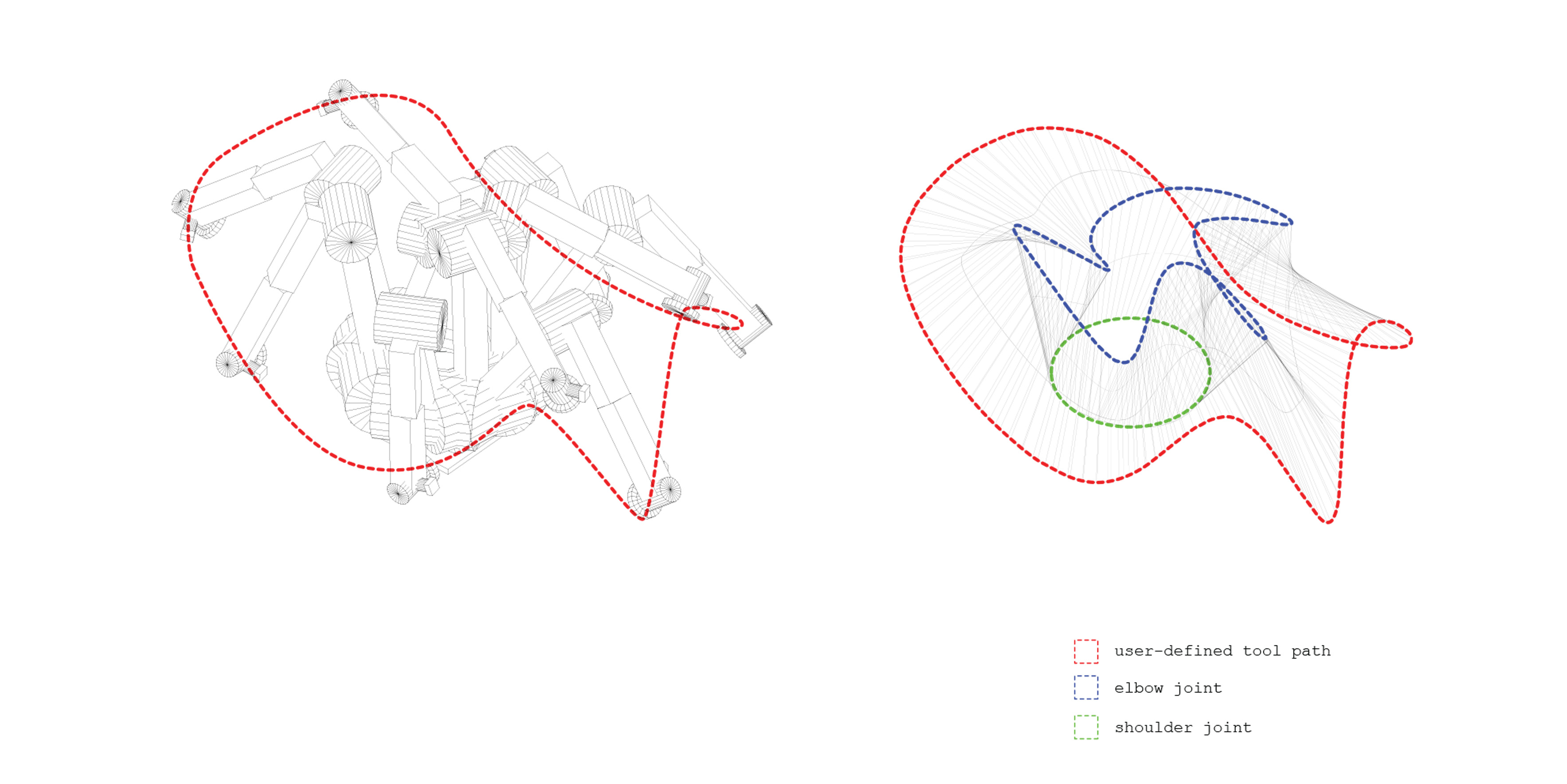 Digram showing the resultant movements of the robot shoulder and elbow joints (right) which executing a user-input end-effecctor tool path (left).
Using a Kinematic model of a master robot (a configutation file which specifies arm-lengths, offsets and joint attitudes of the robot), an Inverse Kinematic Solver calculates the possible positions of the arm components that satisfy the user-defined tool path along its length.
To visualize Inverse Kinematic solutions, the movements of the robotic arm’s elbow and shoulder can be traced while following a given end-effector tool path in a virtual simulator. Since more than one way of satisfying the end-effector constraints is usually possible, there exists a series of possible joint paths which could be visualized to represent a kind of “solution space” for the given tool path.
 Bidirectional Link: A conceptual sketch diagram showing an end-effector tool path resulting from user-defined joint angles over time.
The current practice of inputing tool paths for the robot arm may be thought of as a hierarchical design process where the elbow and shoulder positions are “driven” by the user-defined end-effector path. Most robot arm programming languages are structured to accommodate this work-flow: the position of the robot and its movements are always related to the Tool Center Point (TCP). Swapping the role of the driver and the driven in this design process could create an opportunity for design exploration.
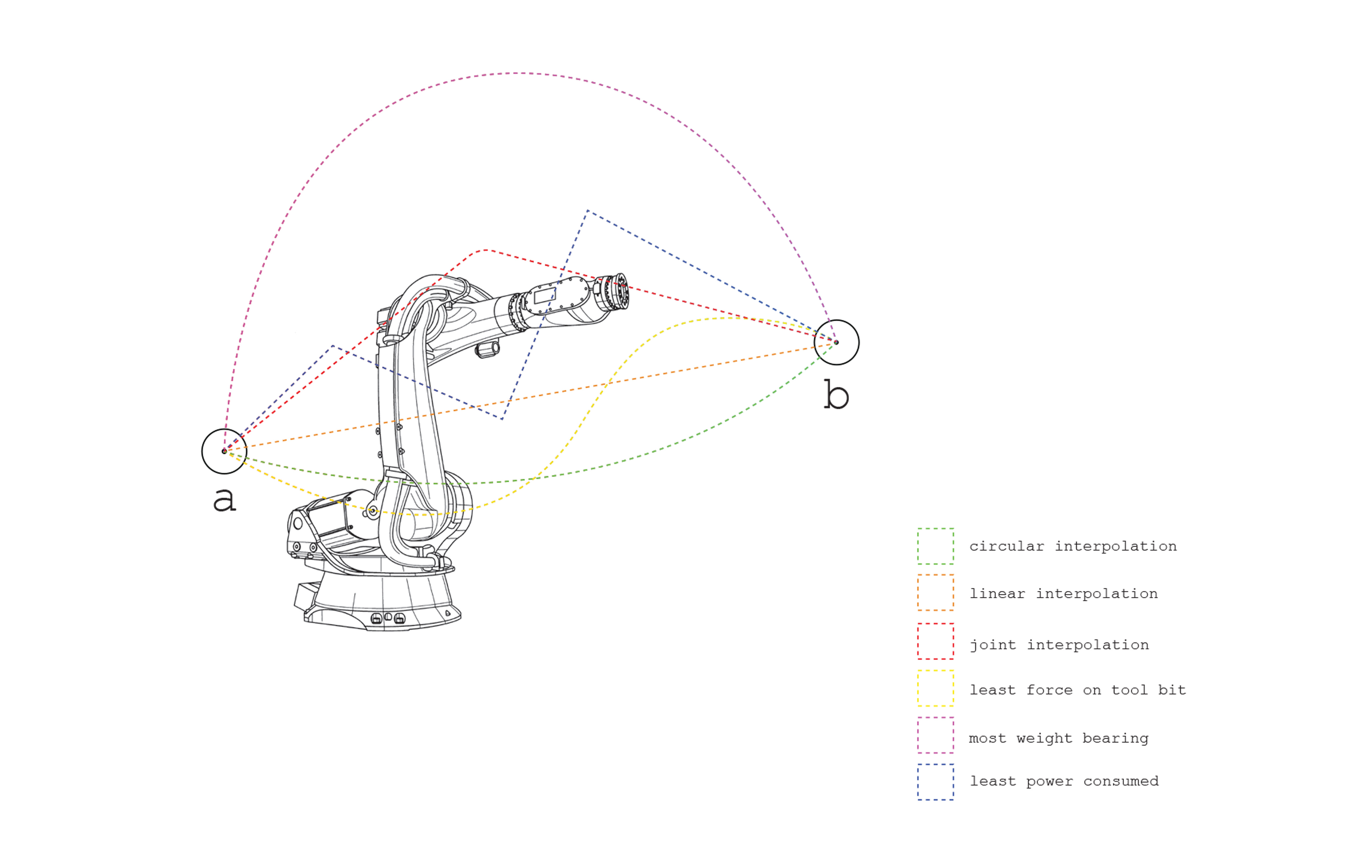
A conceptual sketch diagram showing a comparison of various hypothetical tool paths between two points governed by different optimization priorities.
Most robot arm languages conceive of robotic motion as a series of “pose-to-pose” movements (i.e. interpolating from a current TCP to a new TCP). For instance, the ABB robotic arm can interpolate between TCPs in three main ways:
i.) Linear: the closest path described by a straight line.
ii.) Circular: an arc described by a point defining a degree of curvature.
iii.) Joint: the closes path from the perspective of the axis angles.
While these interpolation methods optimize for minimum distance, custom path-planning algorithms could be developed to allow for interpolation based on other priorities. For instance, using an experimentally derived map of energy consumption based on motion within the robot arm’s work envelope, an algorithm could be developed to compute a path between two fiven points based on the least energy consumption for a given speed.
Other interpolation algorithms could be developed to optimize:
-Movement maintaining a certain weight bearing capactity.
-Movement based on degrees of momentum conservation.
-Movement which minimizes force experienced by the drill bit on a work piece.
-Movement based on a level of motor noise.
Comparing paths between the same points produced from various interpolation priorities could prove useful in gaining a deeper understanding of robotic arm motion parameters. Instead of conceiving of a robotic arm as a generic device which can move anywhere inside a work space, machine limitations couldbe uncovered which could be exploited in a constraint-driven exploratory design process.
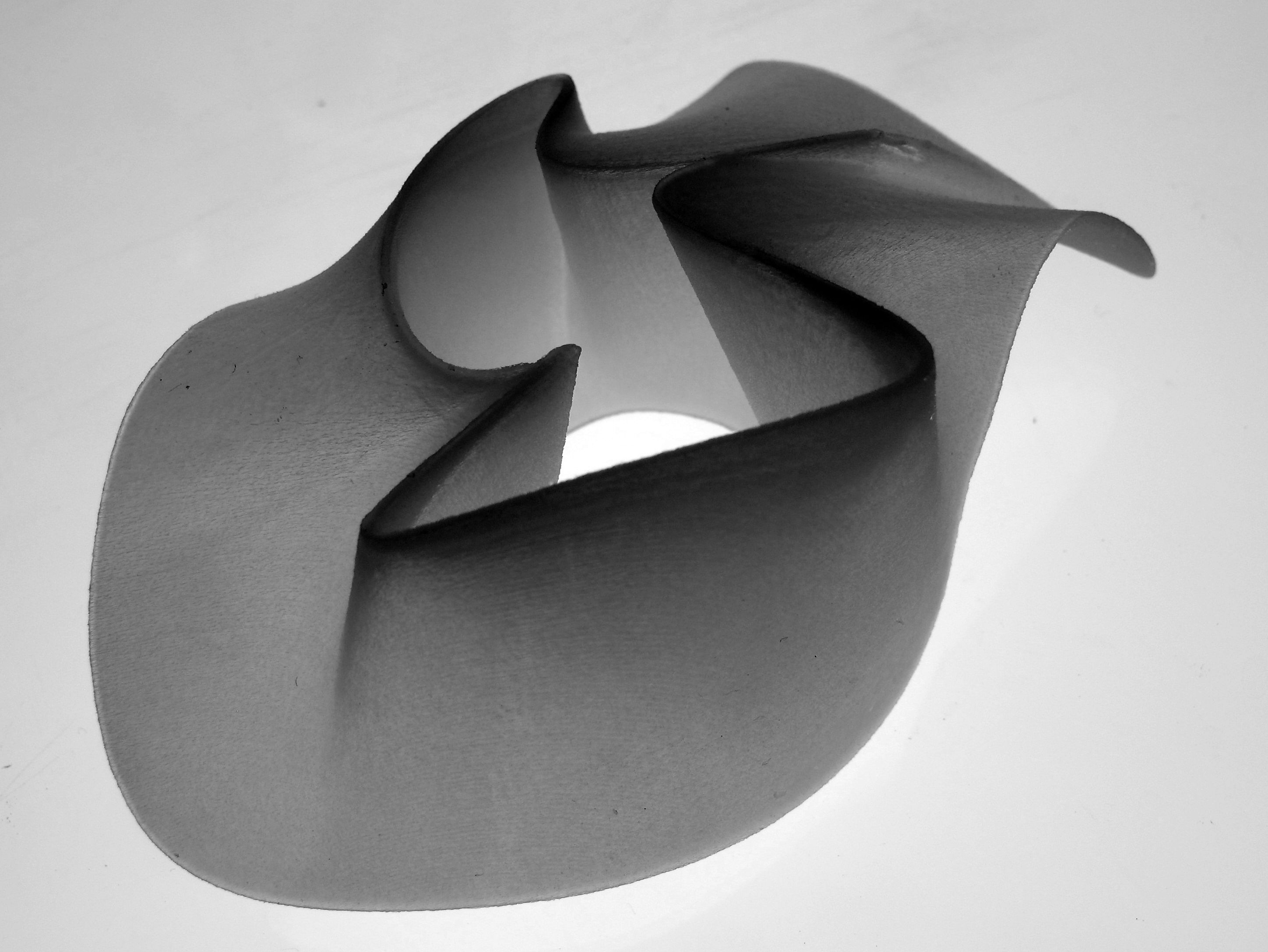
A 3D print on Objet 500 showing the elbow and shoulder movement to accomodate a user defined end-effector path.
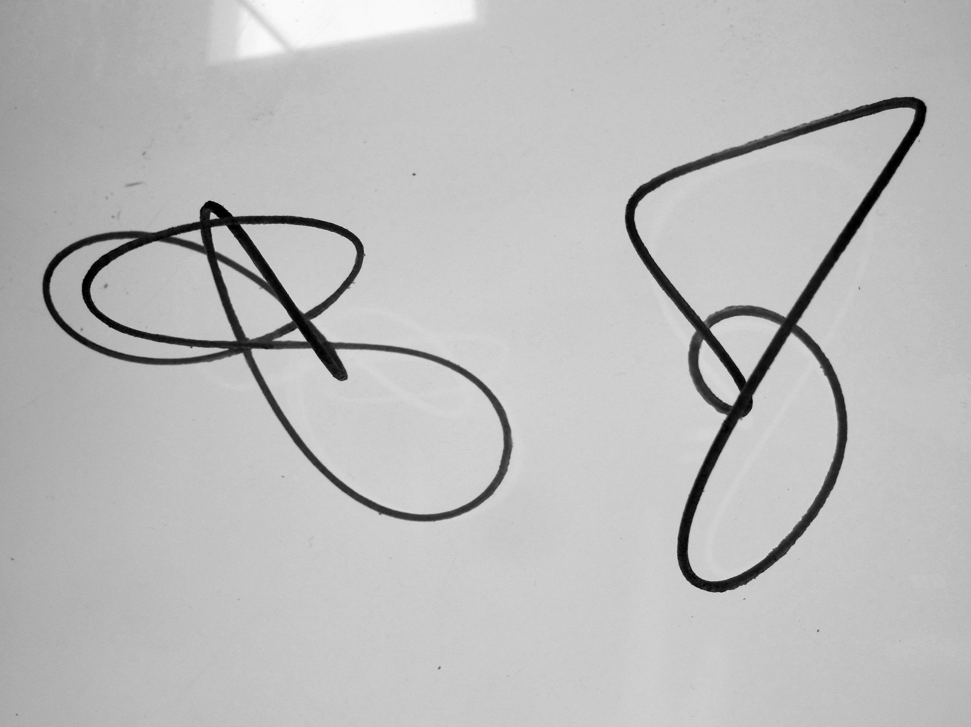
3D print on Objet 500 showing the elbow and shoulder movement to accomodate a user defined end-effector path.
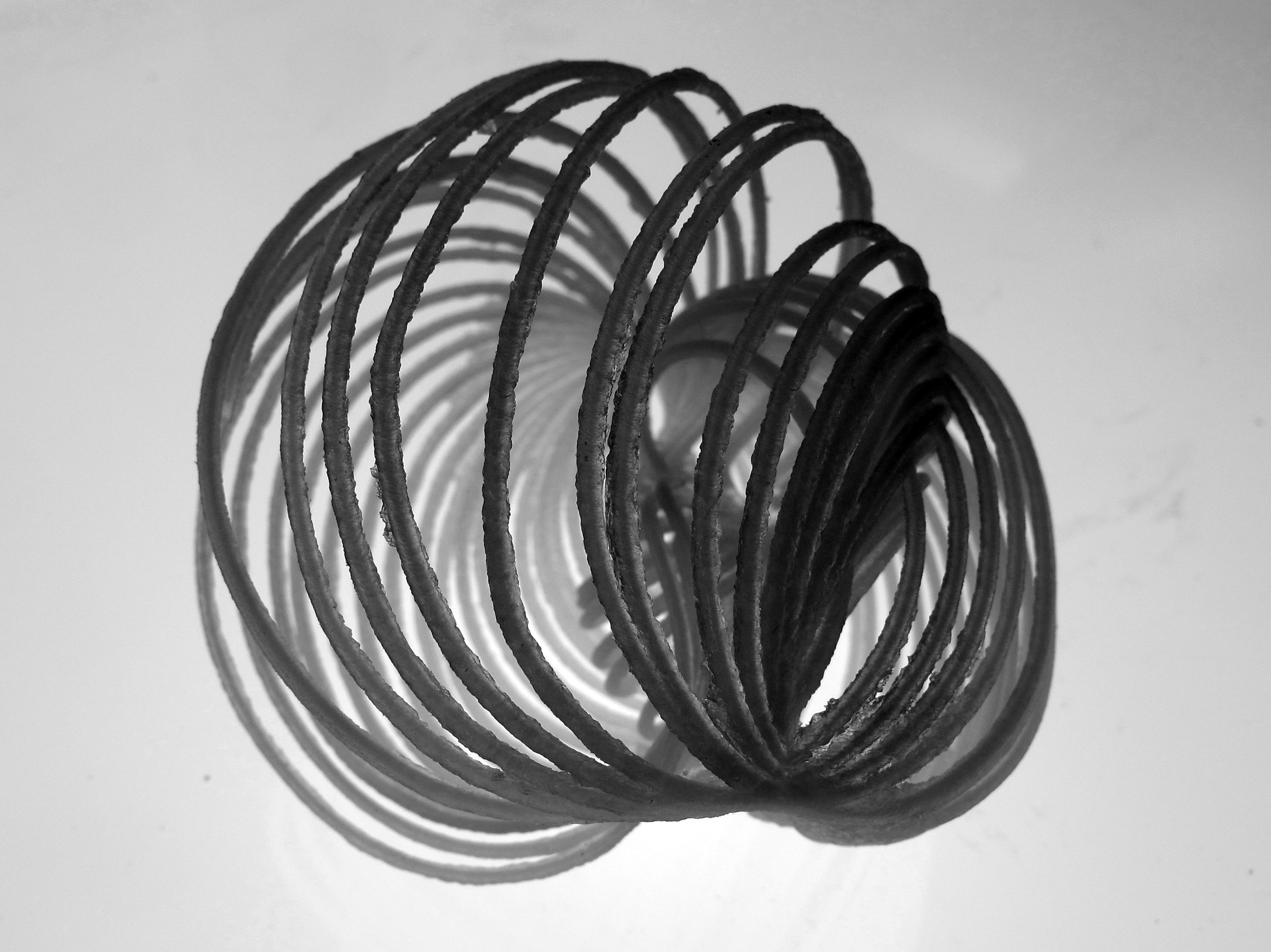
3D print on Objet 500 showing resultant End-effector path from direct control of robot arm joints varying over time.