I want to continue messing around with magnetic media (audio cassette players/recorders, floppy disk drives, video camcorders) and try to get them recording and playing back video.
Here is some inspiration :
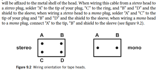
From the timeless Hardware Hacking manual. The suggestion is to use a high gain amplifier to hear the results of the tape pickup. :
A very cool project putting video onto a cassette :
https://www.ubergizmo.com/2020/04/audio-cassette-tape-used-to-capture-video/
From this reply : https://electronics.stackexchange.com/questions/108907/create-input-jack-from-tape-head
“You can use the continuity tester to check for the ground lead. This should be connected to the metal shield of the head, you can leave it unconnected. You’ll want to connect the other two wires to your two inputs”
From this site http://stevecoates.net/walkman/ :

This https://makezine.com/projects/turn-old-walkman-scratchbox/ Make Magazine article connects simply :

Some very cool experiments with a disconnected tape head :
And a custom loop tape :

**************************
I began testing a bit, it looks like I can both see and hear the audio signals from the tape (yellow is R?, blue is L?):
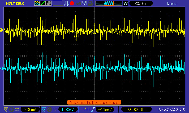
It’s most audible right near the end (the hum is the tape cassette motor spining) :
*****************************************
The method is just to power the cassette rotating motor with around 3.3V, then hook up the red(R?) or white(left?) to a probe or audio in for an amp, and then the black (GND) – which looks like it’s connected to two pins – to GND.
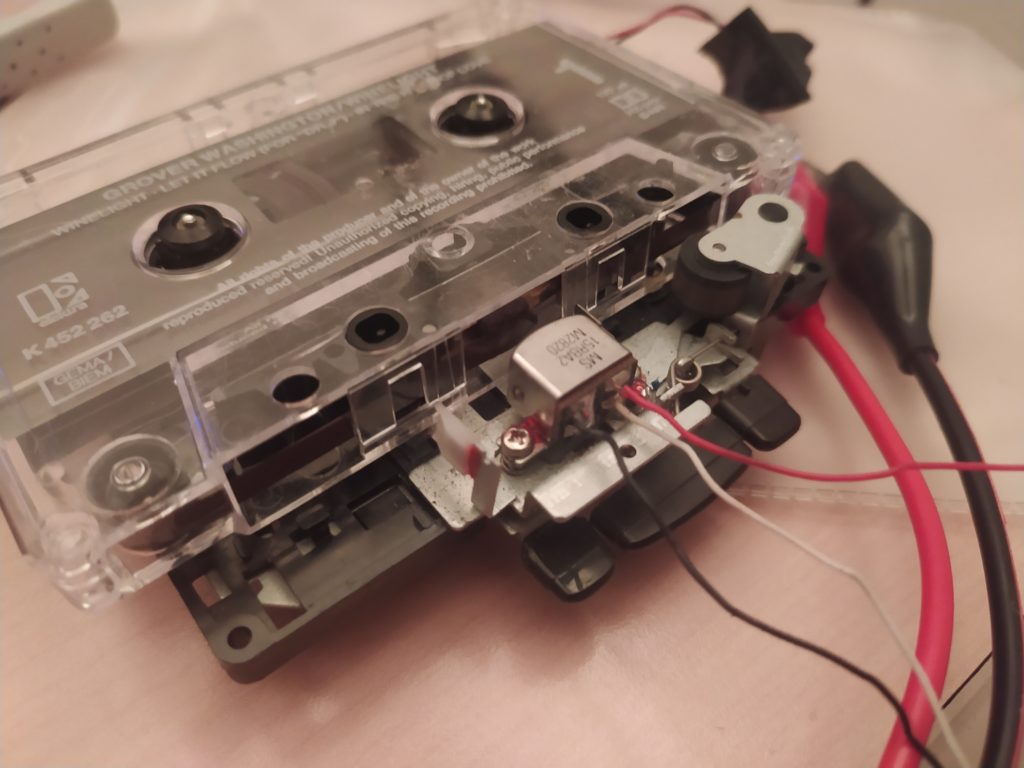
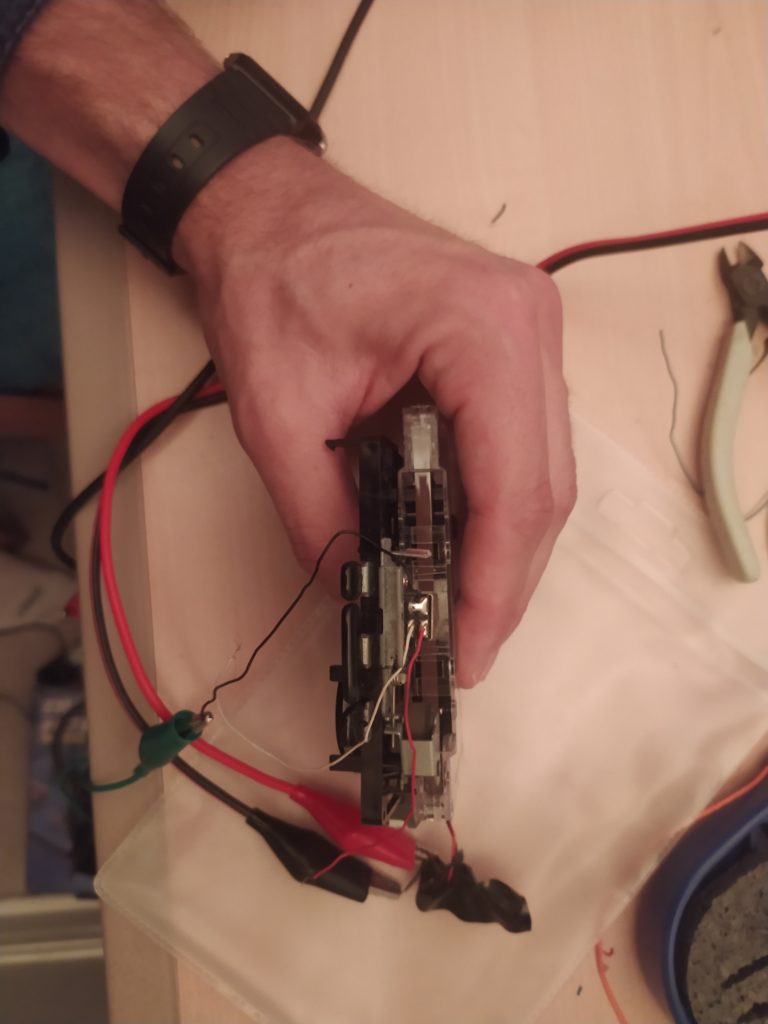
The next step would be to try to amplify with a high gain op-amp circuit ? And then to begin trying to write ?
UPDATE :
Might be easier to work with the electronics already present on the board, learn how it works, desolder it and then put it on a breakout board to mess around with? Here is one of the simplest ICs I found on one of the dissassembled tape decks in an easy to solder SOP16 package:
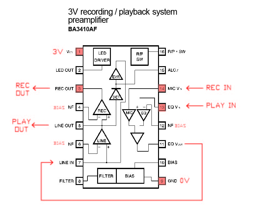
I could order a series of boards like this to make tests with them : 
UPDATE:
I plugged in the little audio amp into the Audio out jack of the device while I touched different pins on the IC. I found that the large slide switch on the back switched from REC to PLAY. I found that during REC mode the pins that caused the most amplification were the MIC IN and EQ IN. In PLAY mode I found the most important pin for producing output on the AUDIO OUT was LINE IN.
I also tried connecting the little speaker amp to the REC OUT, LINE OUT while I touched various pins.
I was unable to amplify the tape head signals however with any of the various combinations I tried. I will try the other tape cassette circuit boards to see if I have any more luck, and also test the 2.5W power amp from Adafruit. Ideally I would be able to take an input, amplify it, send it to the tape head, then read it back by reversing the sequence after rewinding to the same section. This should also work with a strip of tape taped to a desk that I can manually run the magnet head over (right??).
Once I’m able to do this, I want to try the same thing (amplify an analog signal, write it to the disk through the heads directly, then read the analog signal back off it) with the Floppy Circuitry.
*************
A great VCR technical reference : https://www.wikiwand.com/en/VHS
I got my hands on a VCR, took it apart and broke out the cable coming from the helical read/write head.
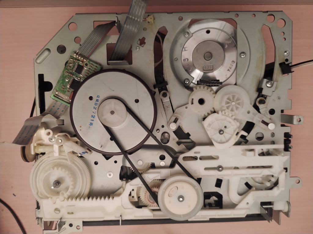
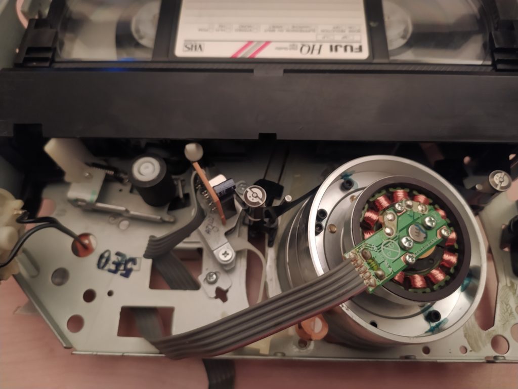
It looks like there is one little board with all the drivers for the various motors. Might be able to control it. (See this video : https://www.youtube.com/watch?v=4F7xJOb32GI&ab_channel=LifeOfDiy). I’ve got a BA6878EFV 3-phase motor driver for VTR capstan, datasheets available online. It looks like you need to plug in GND (3), 5V (2), and then connect EC(7) and HYS OUT (9) together.
So far I haven’t been able to pick anything up on the oscilloscope from moving the tape across the print heads while listening in to various output pins.
https://www.wikiwand.com/en/VHS#Media/File:Medion_MD8910_-_VHS_Helical_scan_tape_head-8601.jpg
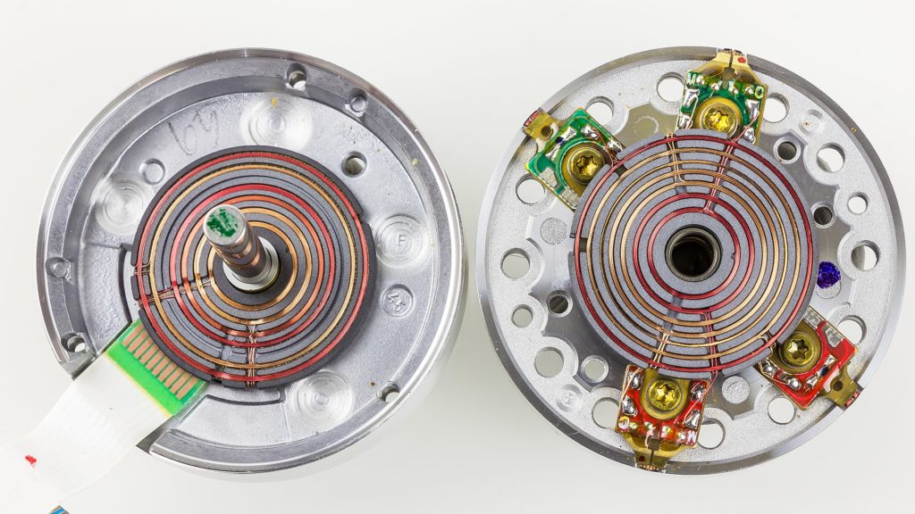
There appear to be two video heads (with two wires each – one wire for each electromagnet) and two audio heads (with one wire each) making a total of 6 wires with 1 dummy. It looks like the pinout is the following :
- Video Green 1
- Video Red 1
- Video Green 2
- Video Red 2
- No connection (shortened turn)
- Audio Red
- Audio Green
It seems like others have two shortened turns to help isolate signals from one another.
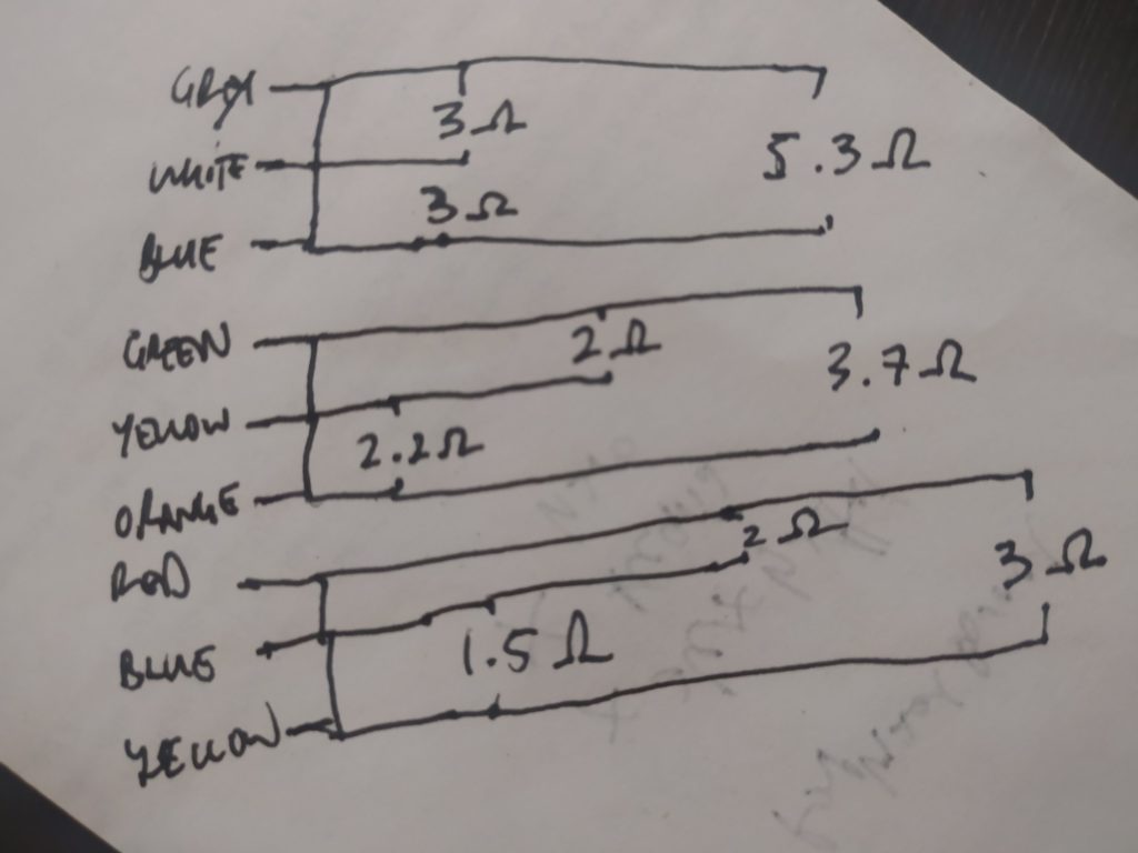
I measured the resistances between the output pins:
- grey
- white
- blue(1)
- green
- yellow(1)
- orange
- red
- blue(2)
- yellow(2)
The following are connected :
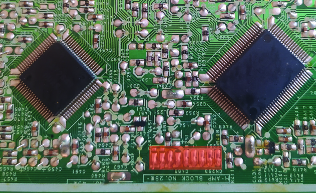
Looking up the chip LA71750 ( Video and Audio Signal-Processing IC) – on the right in the image below – and the LA7264B (Audio Signal-Processing IC) – on the left – and checking out the datasheets and inspecting the PCB, looks like the following are the important connections :
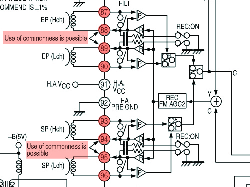
From the LA71750 datasheet :
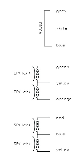
Would appear possible to make this pinout diagram :
I have tried connecting pins to the oscilloscope while moving the tape head, but even at 10mV level at various time scales I can’t see anything.
UPDATE : Just seeing now that this chip takes control data in the form of I2C. It would be super hard for me to desolder the chip and make my own controller with it as a result.
******************
I have tried amplifying and sending 20V signals at various frequencies.
Turning to more research for answers, check out these links :
Article about audio sampler made from floppy :
https://nime.pubpub.org/pub/uh76shf0/release/1
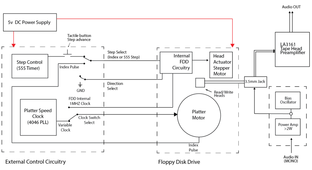
Video made from floppy :
Freespin is a demo made for the Commodore 1541 – no, not the computer, just the floppy drive
For more tech info about floppy heads :
http://forums.openmusiclabs.com/viewtopic.php?f=11&t=92&sid=9a4c3a6763f9bc02426c9d3910187e70
******************
From this reading break I think the following things should be attempted :
-with a >2W class D amp can I push some signal onto the tape that I can then read ? (Just afraid that it won’t be fast enough for video signals as it is made for audio signals ? Perhaps a high power high speed amp is even better?).
-I could get the same preamp LA IC used in the concentric sampler paper.
-Everyone seems to say, “try different combinations with the R/W heads” and “check continuitiy” and apply the signal to continuous wires.
-I could try adding the bias oscillator to the signal I’m trying to R/W?
-I should get a super strong magnet for testing purposes
***********
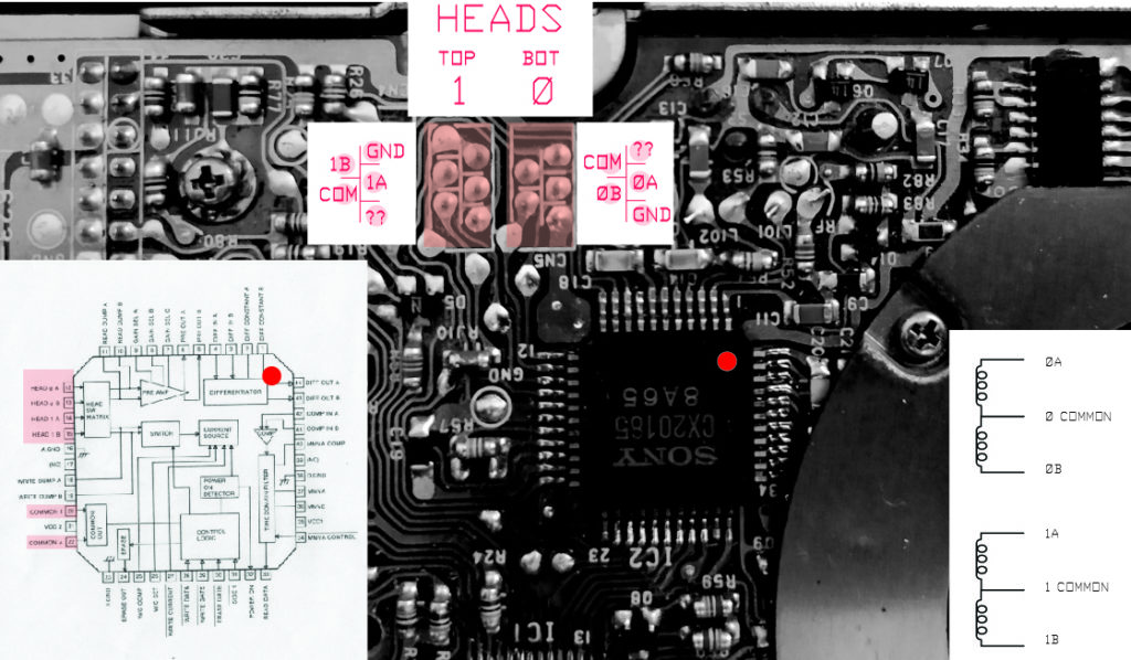
Looking at my floppy drive, I found the following CX20185 chip which is a Read/Write Amplifier for Floppy Disk Drive.
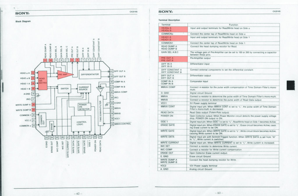
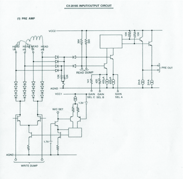
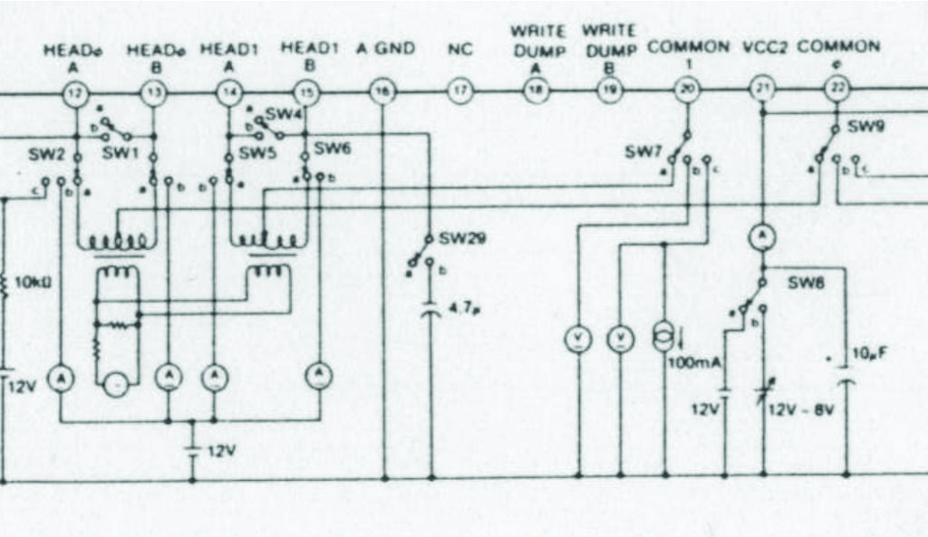
It looks like the pinout is the following :
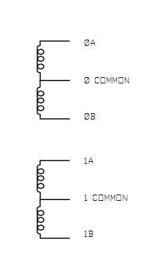
It looks like I could read the Preamp Out pins to read from the floppy. I’m not sure how I could yet wright to the floppy without giving data to the logic on the driver.
Here is me figuring out the pinout :
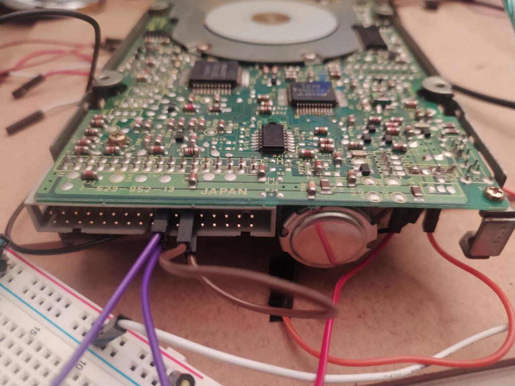
I turned on the floppy LED I have by connecting the sixth pin next to the stepper head motor to the GND, and turned on the central motor by connecting the 8th pin to GND and plugging in 12V as well :
When I listen in to READ DUMP A or B I can see voltage when I spin the disk manually (when I plug in the brushless motor it no longer responds to spinning):
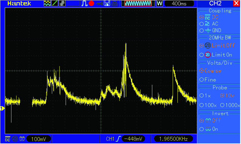
When I listen in to PRE OUT A or B I can see the normally high voltage go down and vary :
Meh.
Some stuff about data degredation :
https://fr.wikipedia.org/wiki/The_Disintegration_Loops
******
Suggestion from research engineer at DVIC for the previous experiments:
-For the floppy, look at the input from head (but oscilloscope will probably mess this up), preamp, and digital out (READ OUT – which should be connected directly to the chip I have the datasheet for) at same time.
-Basically you’re not going to see anything on the oscilloscope when looking at these electromagnets. It’s all in the very sensitive amp – so all the more reason to use the amp that comes with the device !
-Is the preamp chip IC I am looking at even enabled ? Check POWER ON.
-Try the floppy pinout here : https://old.pinouts.ru/HD/InternalDisk_pinout.shtml
-For the VCR, get the thing plugged in and functioning as it was in the beginning. Observe it first, then try to intervene (you’ll never be able to reinvent the thing from nothing !)
****
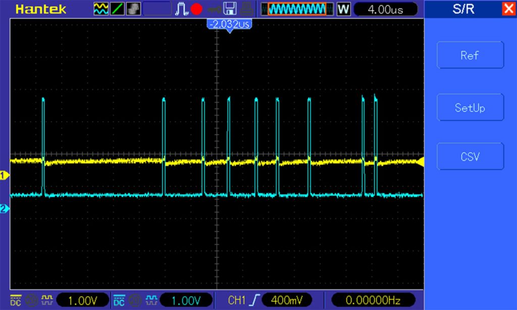
Listening to the DATA READ pin 33 while the disk is spinning :
****
UPDATES:
I learned from watching this (https://www.youtube.com/watch?v=DdMOGvKjrfk&ab_channel=JeffHxC2001) that the way to read is to sync the oscilloscope with the INDEX pulse. The Difference Out pin is the one being listened to in this video.
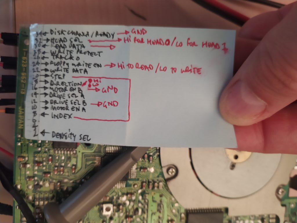
I learned from looking more into the floppy interface that the Head Select (32) is HIGH for BOTTOM and LOW for TOP head. I also learned that Floppy Write Enable (24) is HIGH to READ and LOW to WRITE. Finally, the READY pin 34 may need to be tied to GND.
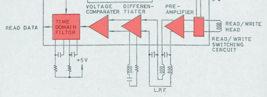
From a Floppy Maintenance Manual showing the sequence : R/W head > Pre-Amp > Differentiator > Voltage Comparator > Time/Domain Filter > DATA OUT
UPDATES:
I think to make this project work, I would first need to *VERY CAREFULLY* observe the correct functioning of a working device without any changes made to it. I would need to be able to confirm completely the working of the machine, and see what signals are supposed to look like at each step.
Only after doing this could I start intervening in this process.
I think Floppy is the best way to go – it’s part of the history of the computer (like all my other projects) which isn’t the case with the video recorder. The floppy is the best documented, easiest to source, and least expensive to work with. It already has a nice interface which is easy to use. It also is more standardized, unlike the many different kind of video recorders that exist.
What is the most standard Floppy Drive Read/Write Amplifier ? The Sony CXA series (1360, 1720, 3010, 3071, 20185, etc.) seem to have specs available online. ROHM also have BH6xxx and BA6xxx series.
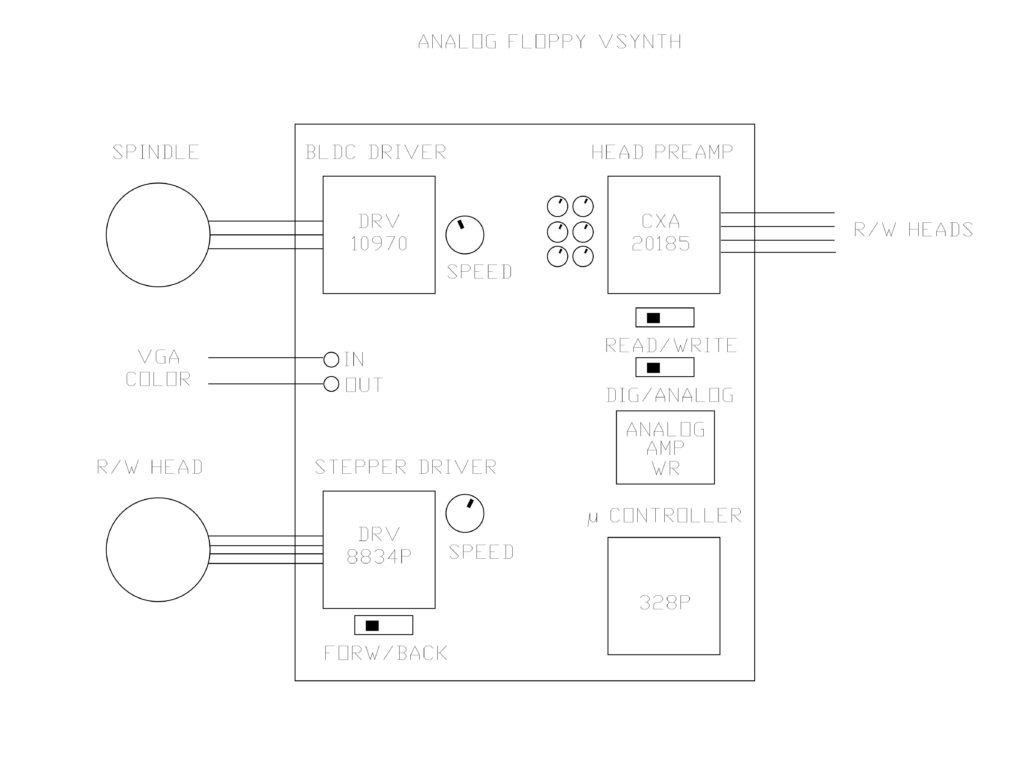
Then again if I’m only going to be recording analog, I don’t need anything but the preamp (especially for reading) ? I could just take the tape preamps I have and put them on a breakout board ? I have BA3110, CX20023, and a CXA1262 to work with. I could try getting them to work amplifying the mic first, and also get the playback working. Then I could test putting analog signals on a floppy.