Electronics Education Kits
Solar-Powered Mini Rover
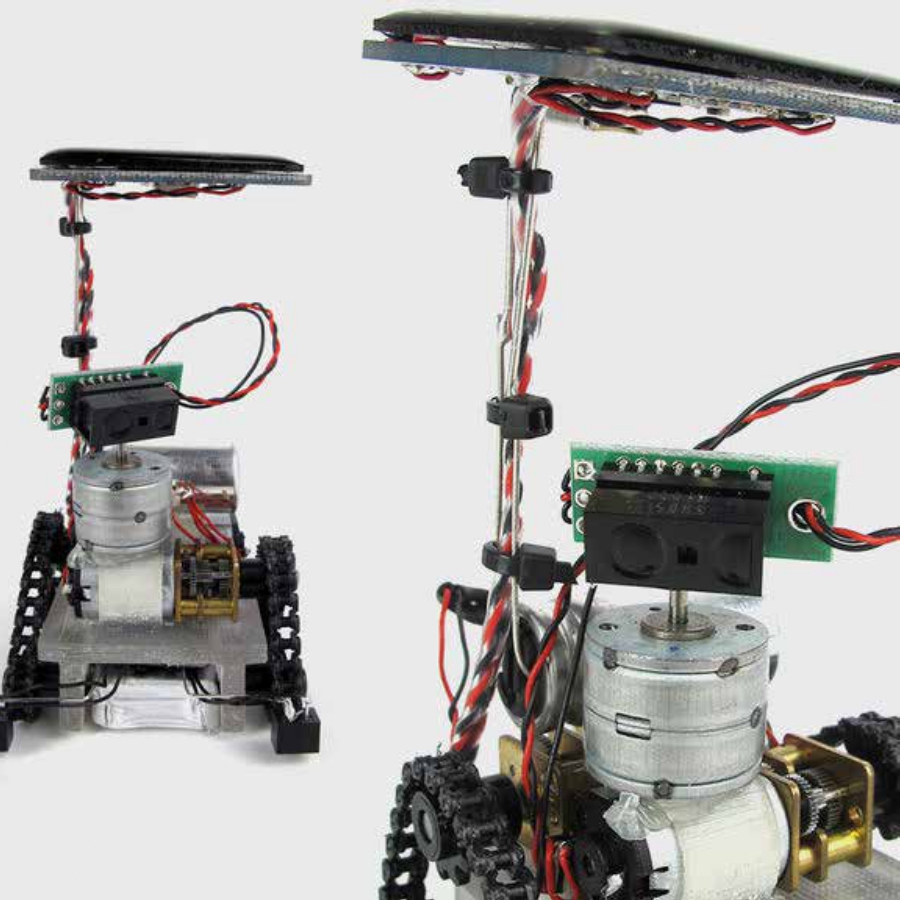
The goal of this project is to develop a miniature chassis to experiment with very basic swarm robots. The prime inspiration is James McLurkin’s fantastic MIT project from the early 1990’s http://www.ai.mit.edu/projects/ants/.
Features:
-Approximately under 2″ cubed and designed to be compact.
-All electronics powered by single Lithium Ion Battery (3.7V).
-All electronics relatively inexpensive (sensors all under or around 7$ each),- though the chain drive is a bit costly.
Aspiration:
-To develop a solar recharging group of mini autonomous robots which can be experimented with and perhaps one day perform basic demos (sorting skittles, plotting basic shapes, etc.)

The next version of the robot involves a custom solar charging circuit based on the LT3105 and a super capacitor instead of a lithium ion battery.
Solar board:
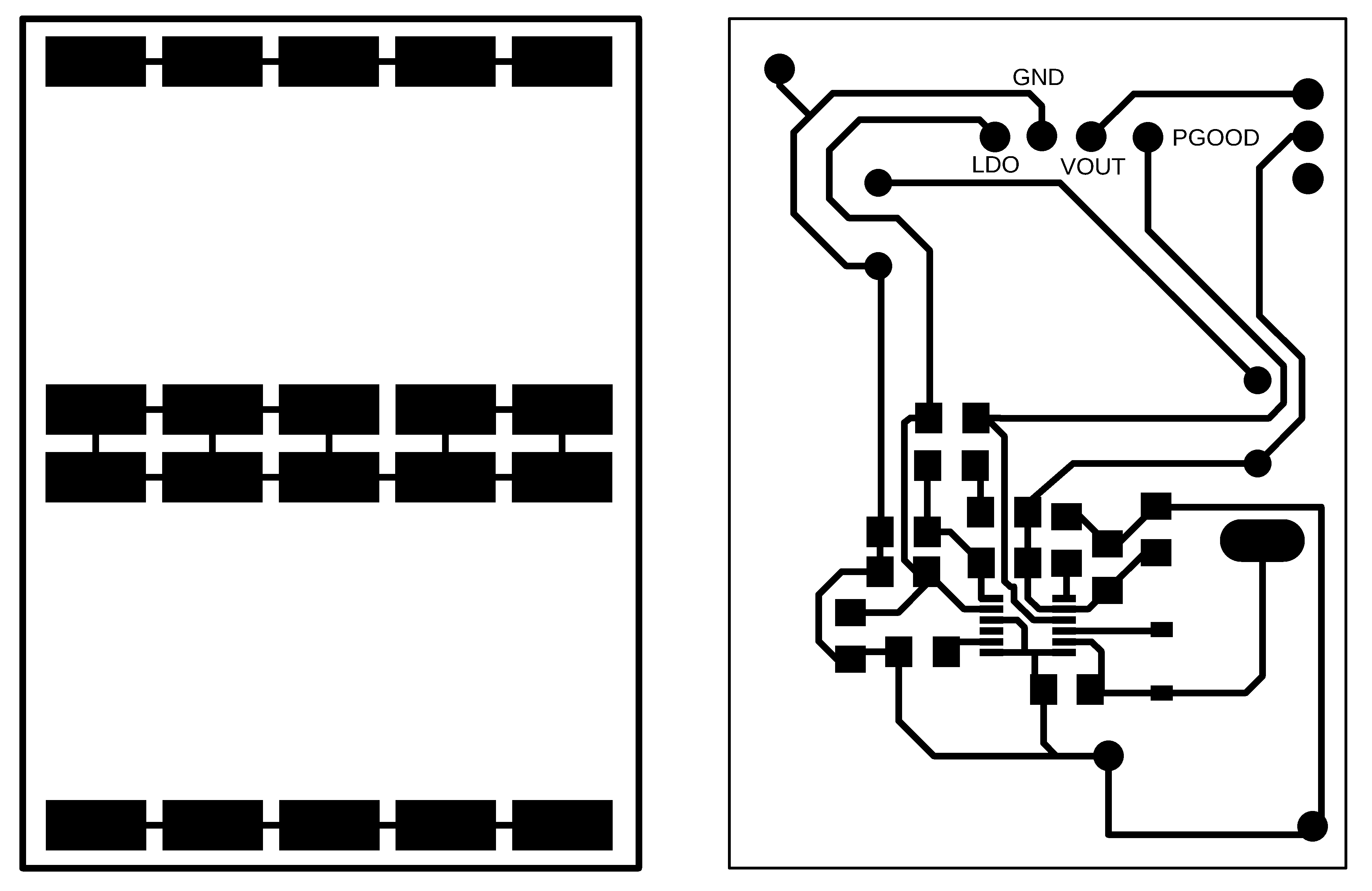
microcontroller board:

Errata:
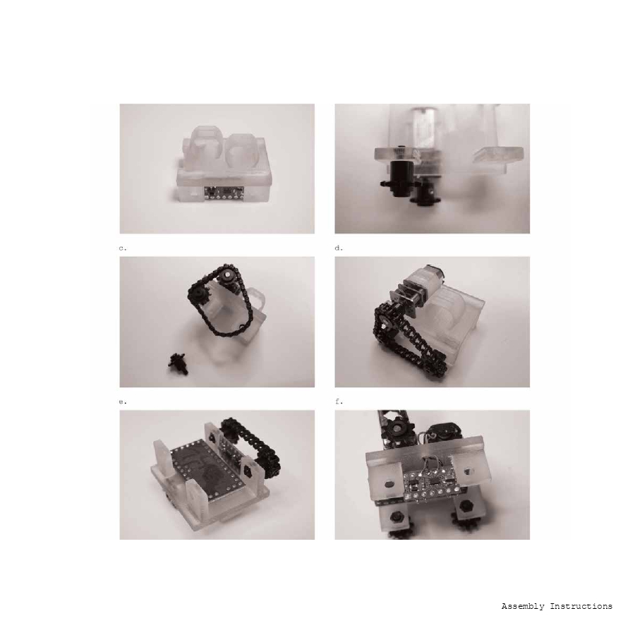
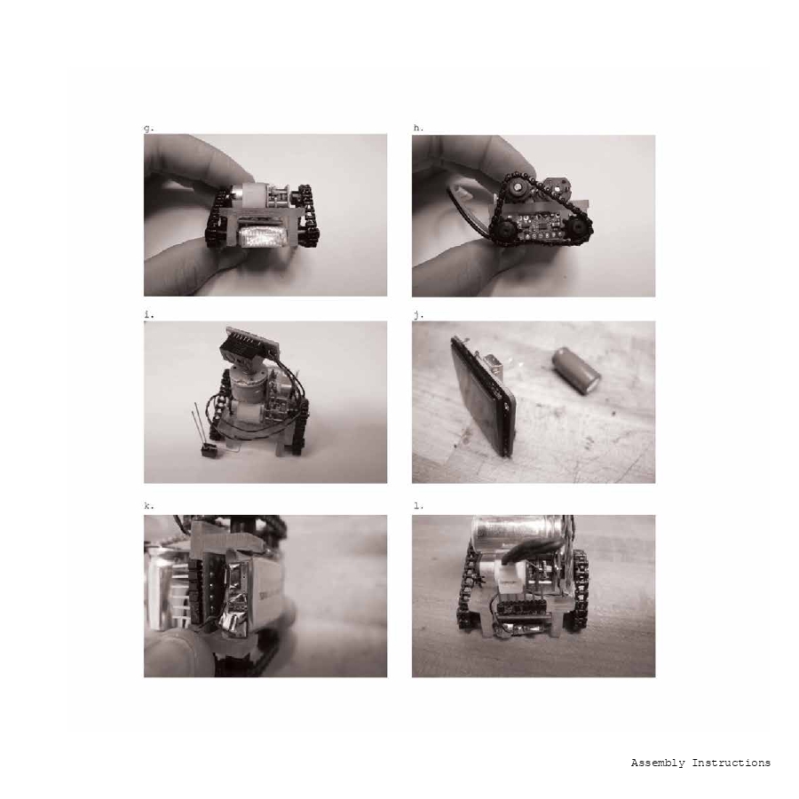
-I need mini jumpers (with tiny wires) to make the motor connections and connections between boards. This is the most annoying thing with the current iteration.
-Threading everything through the chassis is also painful, perhaps the chassis should be C-shaped so that everything can be soldered and then inserted afterwards.
-My 3D model of the chassis didn’t have the motor mounts…Gluing them with a hot glue gun was not optimal.
-In general everything should be a little bit more spaced out, it because excruciating to solder and cram all these tiny things together again and again.
-This should be done with a proper PCB with vias to avoid all the wiring.
-The solar panels I used have a max of 2V but they more often produce 1V, which is well below the 2.5V where the LTC3105 is most efficient.
-I should incorporate the edge sensors into the final pcb design.
-I have no proper solution for a mast to hold the (kind of heavy) solar panel portion of the robot.
Here is the Arduino code I’m developing for a first test:
/*
* TEST CODE
*/
//PILOTE DE MOTEUR
const int SLEEP = 4;
const int AIN1_ = 6;
const int AIN2_ = 5;
const int BIN1_ = 8;
const int BIN2_ = 7;
const int AIN1 = 14;
const int AIN2 = 15;
const int BIN1 = A5;
const int BIN2 = A4;
const int PGOOD = 3;
const int LED1 = 9;
const int LED2 = 10;
const int IR = 2;
const int LDR2 = 16;
const int LDR1 = 17;
const int DELAY = 500;
long randNumber;
void setup() {
//RANDOM NUMBER GENERATOR
randomSeed(analogRead(3));
/*
* OUTPUTS
*/
//pilote de moteur
pinMode(AIN1_, OUTPUT); //
pinMode(AIN2_, OUTPUT); //
pinMode(BIN1_, OUTPUT); //
pinMode(BIN2_, OUTPUT); //
pinMode(AIN1, OUTPUT); //
pinMode(AIN2, OUTPUT); //
pinMode(BIN1, OUTPUT); //
pinMode(BIN2, OUTPUT); //
pinMode(SLEEP, OUTPUT); //
// On board LEDs connected to LDO therefore LOW to turn ON
pinMode(LED1, OUTPUT); //
pinMode(LED2, OUTPUT); //
/*
* INPUTS
*/
//IR sensor
pinMode(IR, INPUT); //
//LTC3105 interface
pinMode(PGOOD, INPUT); //
//Edge detectors
pinMode(LDR1, INPUT); //
pinMode(LDR2, INPUT); //
}
void loop()
{
if (IR == LOW) // no obstacle detected
{
avancer();
}
else
{
reculer();
delay(DELAY);
randNumber=random(300);
if (randNumber%2>0)
{
droit();
delay(DELAY);
}
else
{
gauche();
delay(DELAY);
}
}
}
//function definitions:
int avancer()
{
digitalWrite(AIN1_, HIGH);
digitalWrite(AIN2_, LOW);
digitalWrite(BIN1_, HIGH);
digitalWrite(BIN2_, LOW);
digitalWrite(SLEEP, HIGH);
}
int reculer()
{
digitalWrite(AIN1_, LOW);
digitalWrite(AIN2_, HIGH);
digitalWrite(BIN1_, LOW);
digitalWrite(BIN2_, HIGH);
digitalWrite(SLEEP, HIGH);
}
int droit()
{
digitalWrite(AIN1_, LOW);
digitalWrite(AIN2_, HIGH);
digitalWrite(BIN1_, LOW);
digitalWrite(BIN2_, LOW);
digitalWrite(SLEEP, HIGH);
}
int gauche()
{
digitalWrite(AIN1_, LOW);
digitalWrite(AIN2_, LOW);
digitalWrite(BIN1_, LOW);
digitalWrite(BIN2_, HIGH);
digitalWrite(SLEEP, HIGH);
}