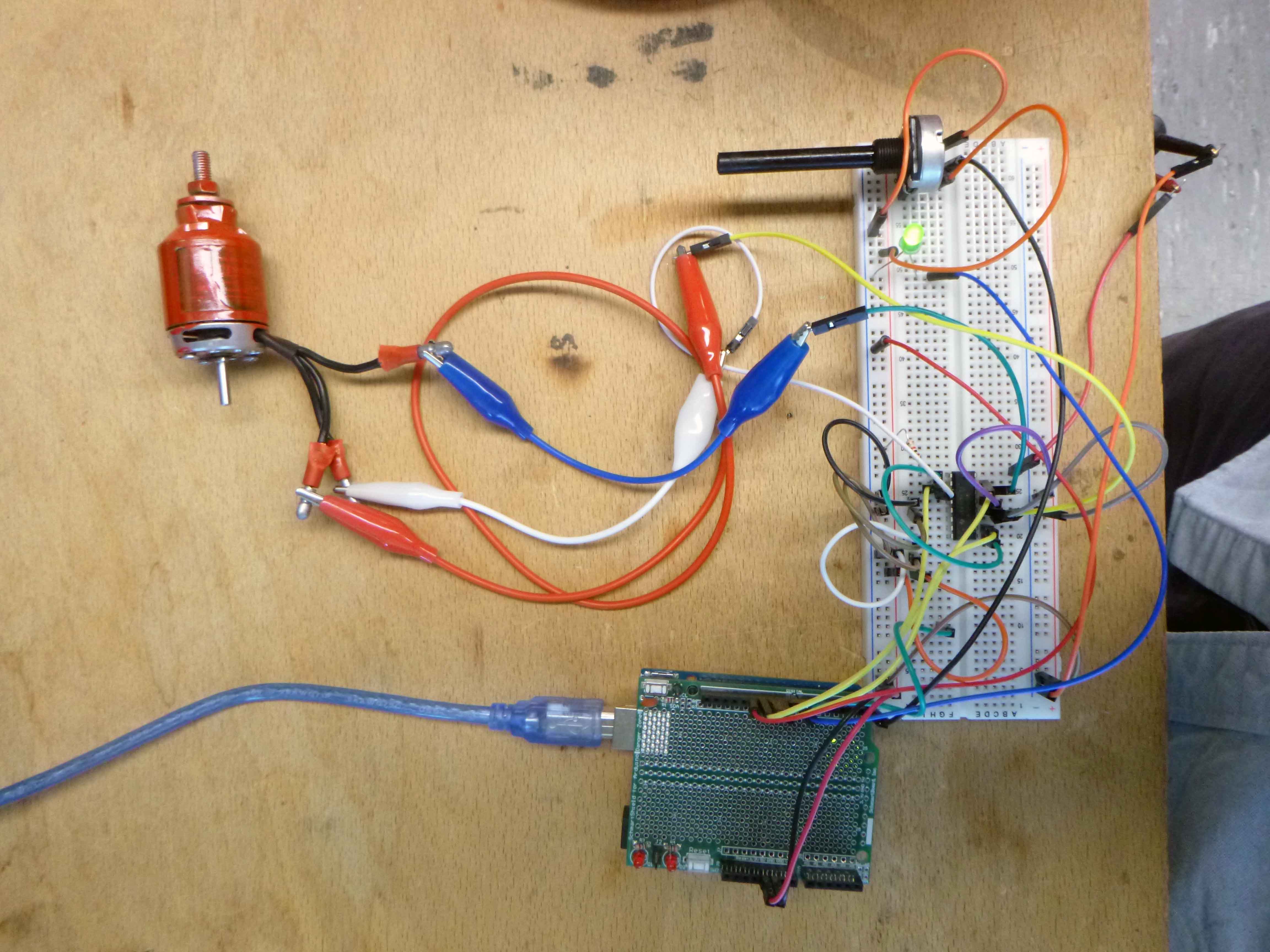
Based on Hackteria’s DIY Centrifuge (https://hackteria.org/wiki/Hacked_Hard-disc_Centrifuge)
Controlling a Three-Phase DC Brushless motor (BLDC) of a Hard Drive primer: https://www.monolithicpower.com/pub/media/document/Brushless_DC_Motor_Fundamentals.pdf
Similar to a stepper motor (except a BLDC is meant to run smoothly not in steps) but with three stators (if it’s an inrunner, an outrunner has the permanent magnets around the shaft):

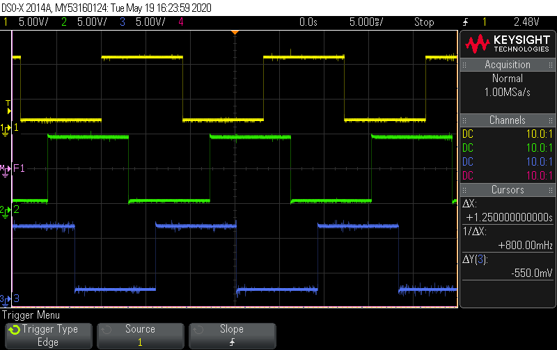
At the top are the signals we need to generate with signal phase 120 degrees offset (steppers are typically two phase with 90 degrees apart):

I’m using the SN754410 Quadruple Half-H Driver IC based on this tutorial: https://elabz.com/bldc-motor-with-arduino-circuit-and-software/
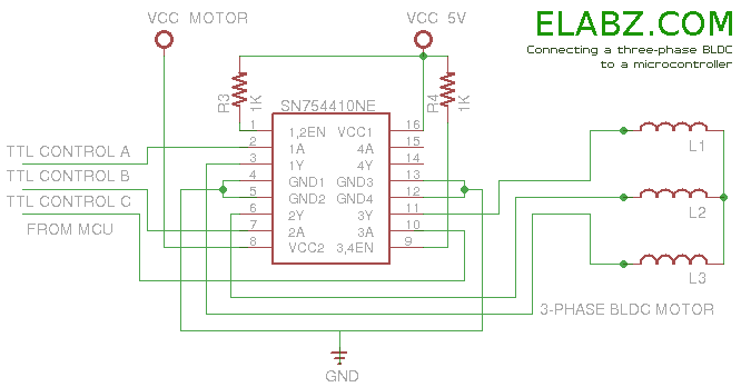
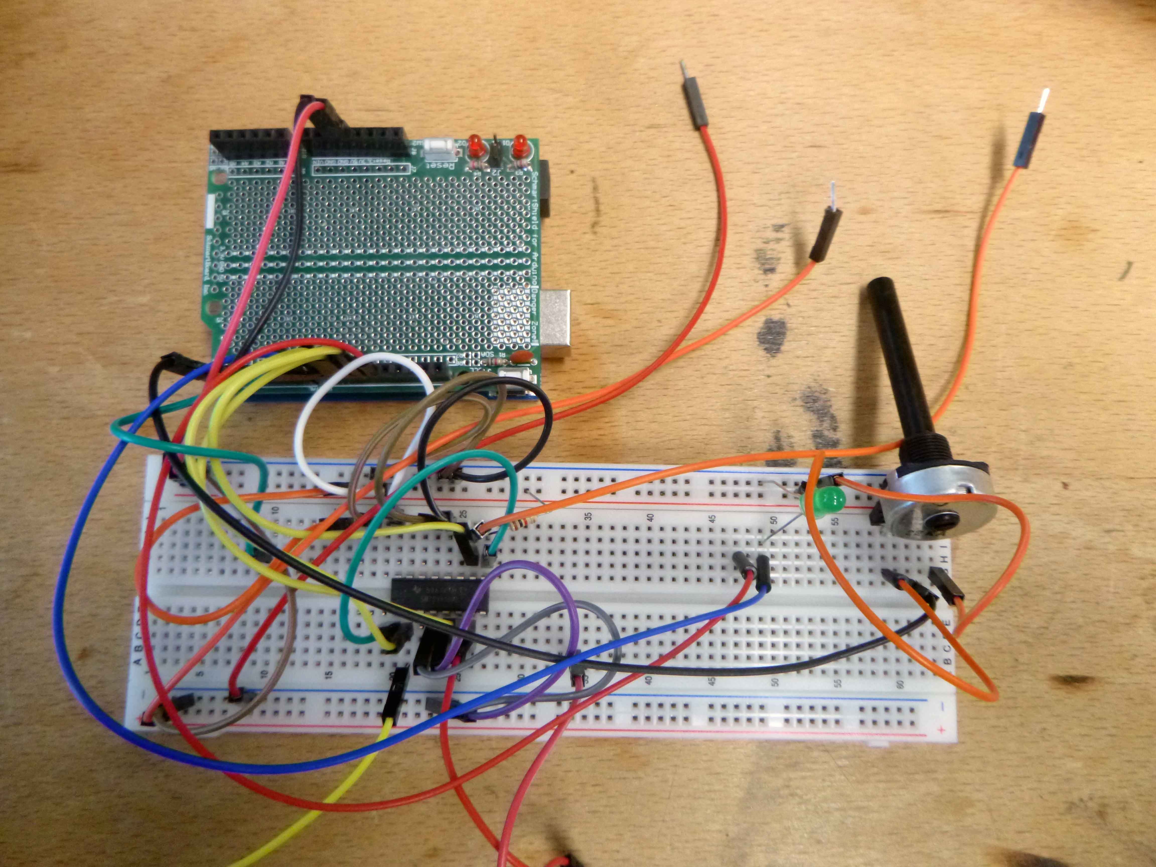
Here’s the circuit breadboarded (motor connection not shown) with a pot to change the speed:
Here is the scope capture of the sigals generated:
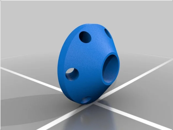
This is the 3D file I downloaded: https://www.thingiverse.com/thing:2539744
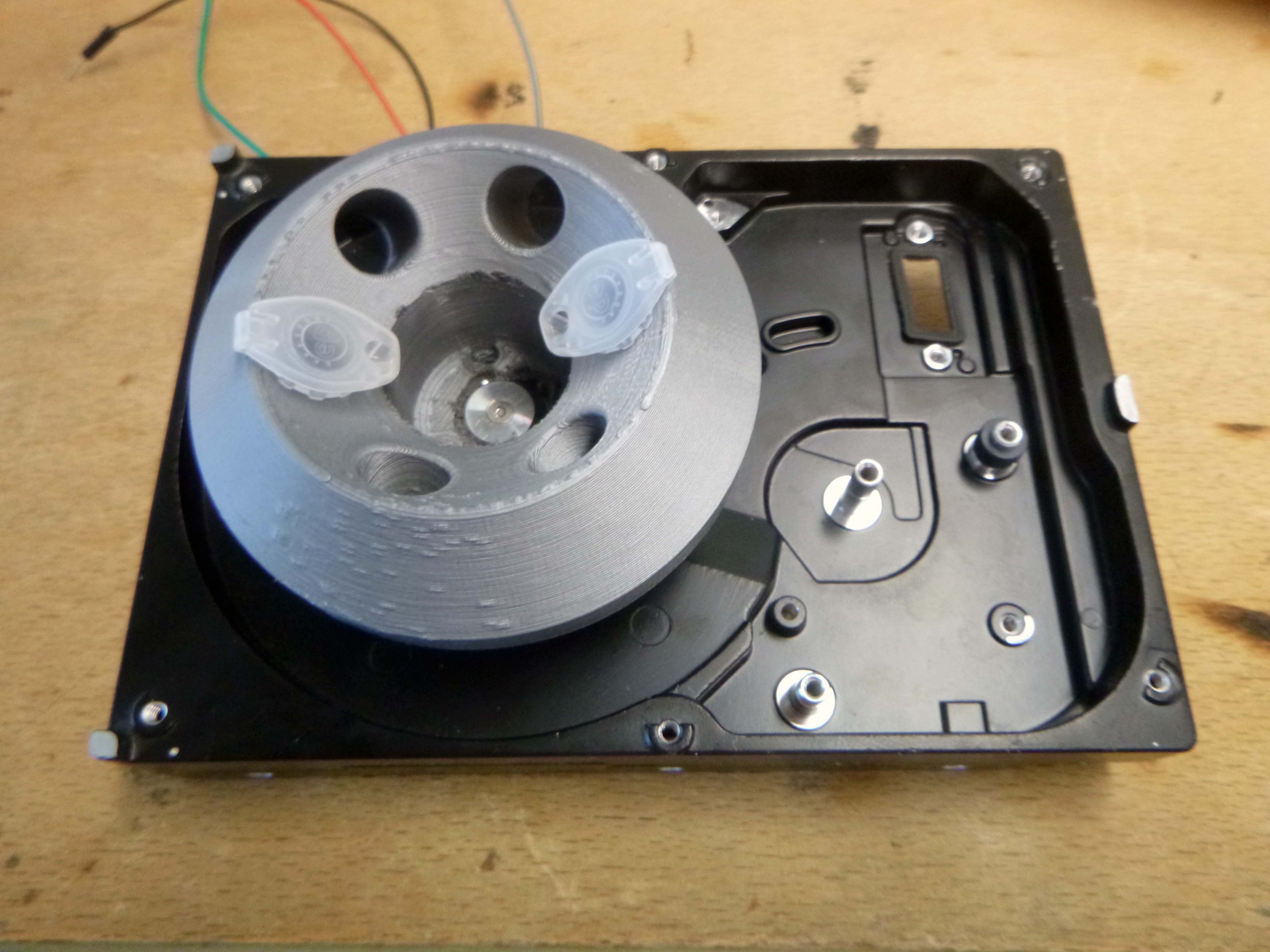
Here’s the 3D print with two 1.5ml Eppendorf tubes screwed on to the BLDC hard disk motor.
I had difficulty distinguishing between which of the three wires were connected to coils and which on wasn’t and got inconsistent resistance measurements. My current thinking is that the motor was damaged and is not working.

Testing with another kind of BLDC and still not working…so is most likely my circuit?
