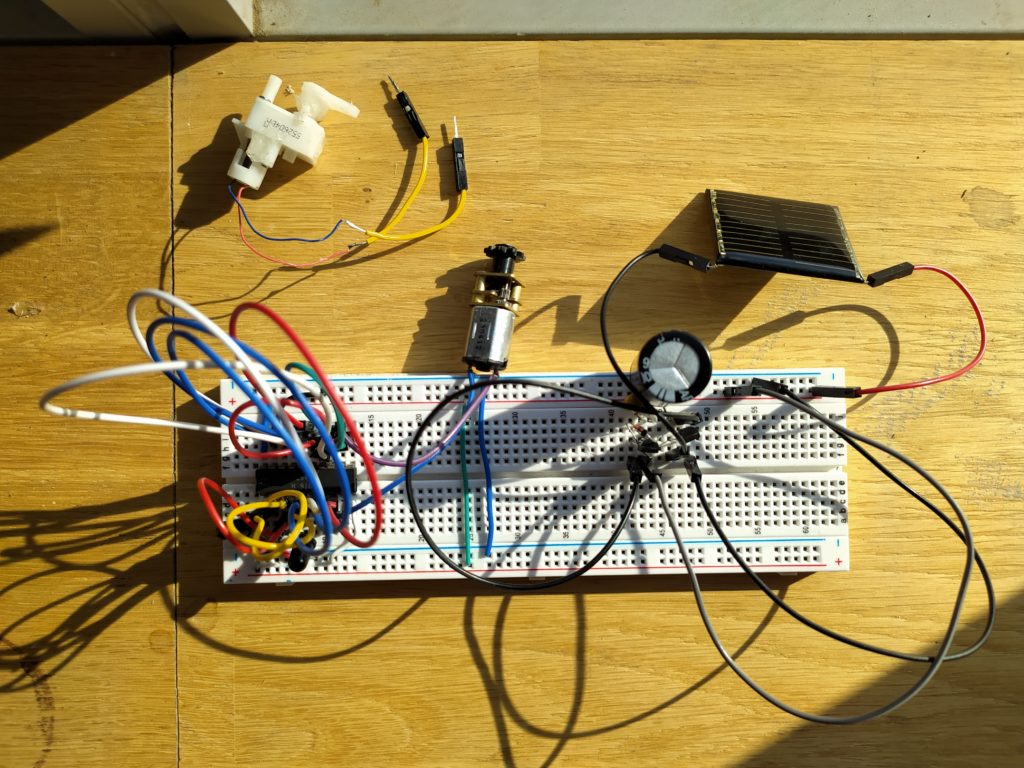
This circuit (found here: http://solarbotics.net/library/circuits/se_t1_1381.html) works with a MCP112 voltage supervisor to save up solar energy until it is significantly large to make turn a motor. With a small solar panel charging a large capacitor, it is possible to make something move even on an overcast day!
The circuit works by charging the capacitor with a solar panel until it reaches the MCP112’s tripping point (in this circuit I’m using the 2.7V tripping point flavor but they range from 1.8V to 4.38V) at which point the MCP112 activates the PN2222 transistor which powers the motor. The PN2907 turns on at this point and latches the PN2222 in the on position until the capacitor voltage level runs below the PN2907 turn on threshold (of about 0.6V). Without the PN2222 the MCP112 would deactivate at 0.3V below it’s trigger threshold (2.4V in this case).
I’m using a 37x33mm Monocrystalline Solar Cell from Solarbotics.com (https://solarbotics.com/product/scc3733/) which produces 6.7V and 20mA. It is at maximum efficiency of 106.335mW with a load of 300 ohms.
By changing the size of the capacitor from 2200uF to 4700uF you can change the amount of charge that will be passed on to the motor.

On an overcast day the little motor is activated every 5 seconds or so for about half a second, not bad for a tiny solar panel!
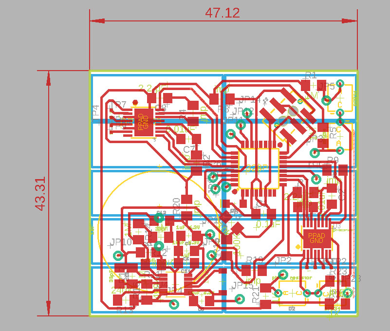
Here’s the trace image showing a comparison of the same circuit with different capacitor sizes and voltage trigger flavours:

Neato!
I am interested in using this circuit to power something other than a motor. However, simply replacing the motor with a given circuit (like a microchip) does not work.
Replacing the motor with a 220 ohm resistor appears to allow the circuit to cause an LED to blink and to charge and discharge, however.
The Complete Solar Power Smart Head Rev.3 by Wilf Rigter
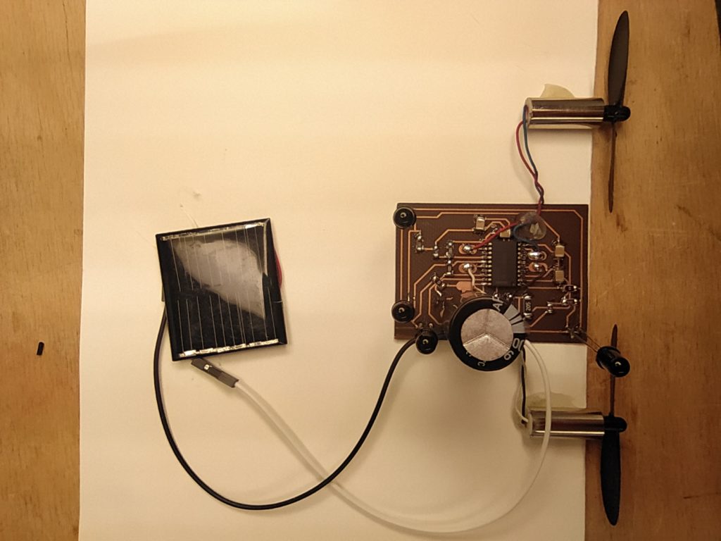
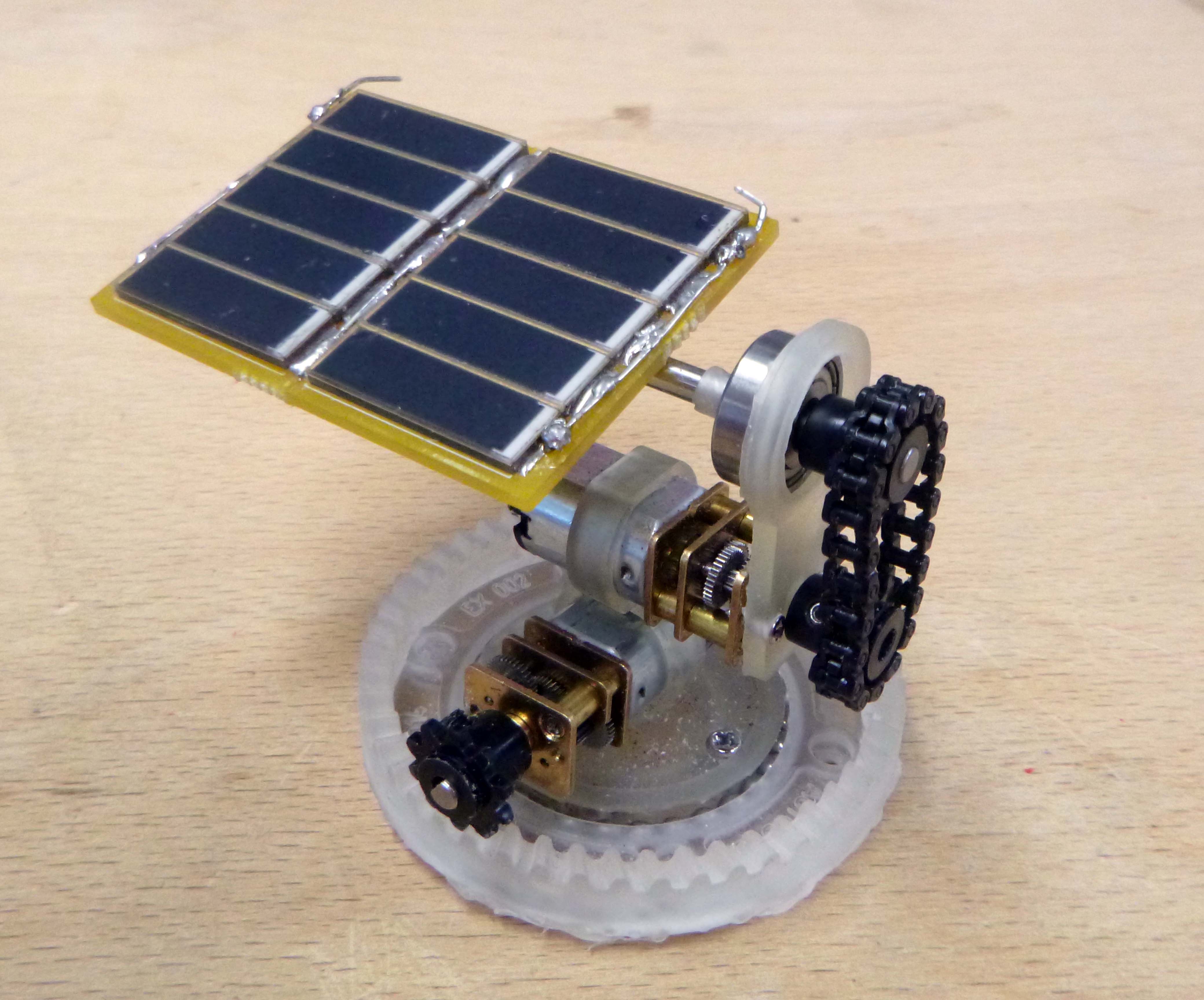
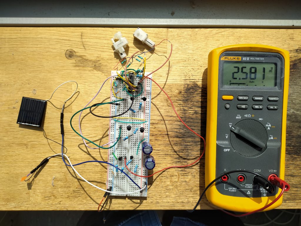
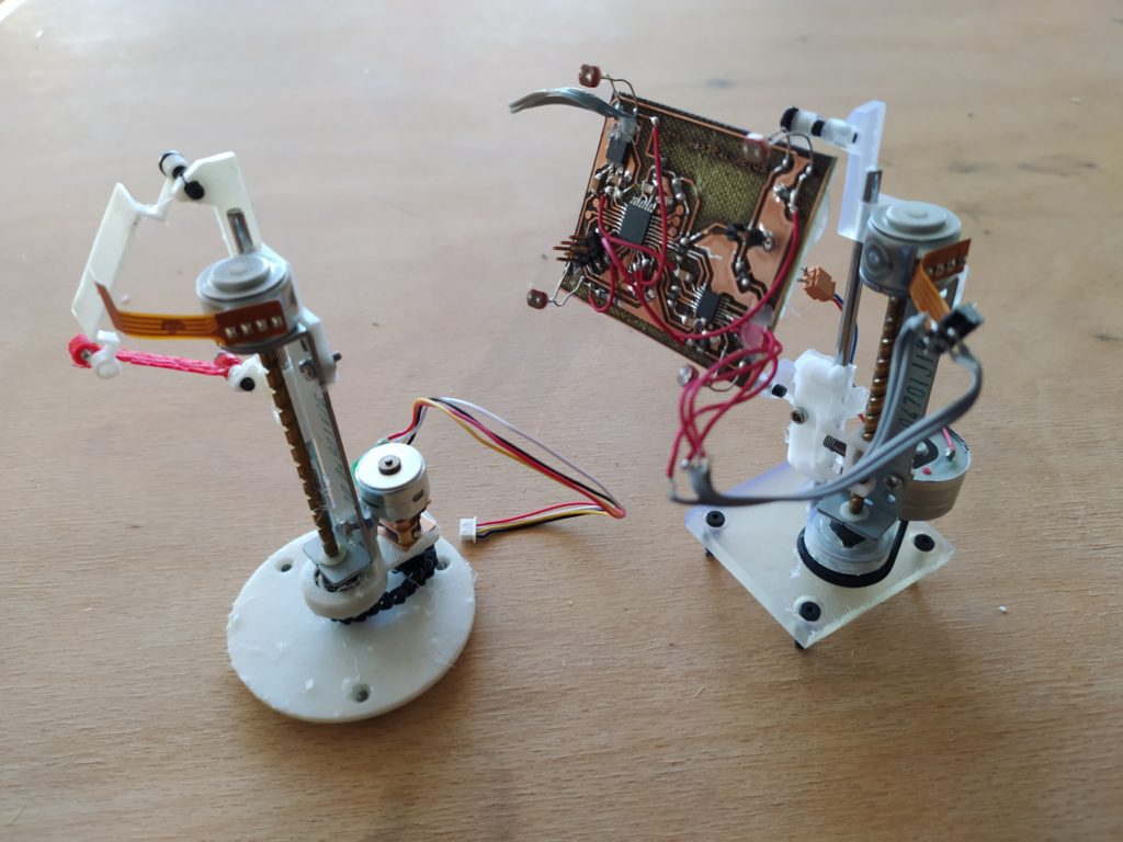
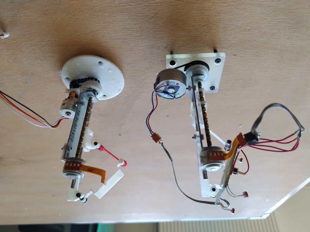
Here is a photo of the full assembly in action!


I found the circuit at this website: http://solarbotics.net/library/circuits/bot_head_pshead.html
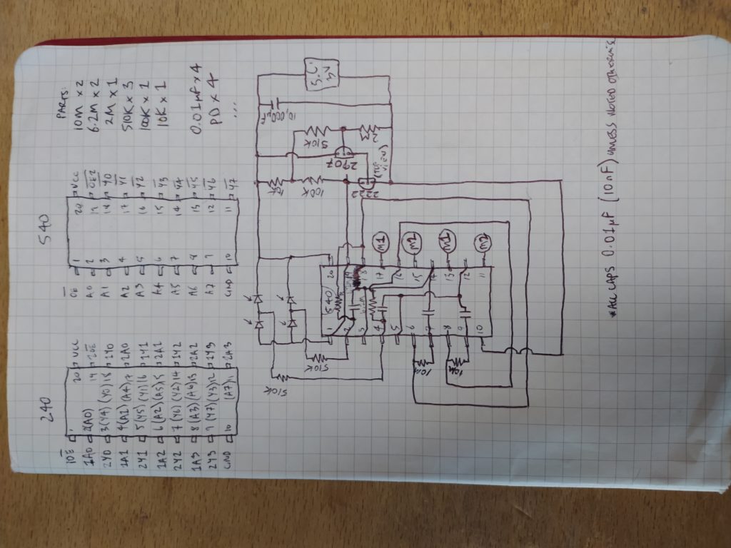
I am building Wilf Rigter’s 74HC240 circuit but replacing the 74HC240 with two 74HC540s (and replacing the 1381 with a MCP112) because I couldn’t source a 74HC240 from my local electronics store. The two logic chips are inverting octal buffers but the 74HC540 has one enable for all eight inverters while the 74HC740 has two for two sets (A and B in the circuit above). To make the translation, first I connected the two AND input enables of the 74HC540 to behave the same way as the single enable of the 74HC240, then I remapped the pins from one 74HC240 to two 74HC540s.
Here is the comparison of the 74HC240 with the 74HC540 and my remapped circuit:


Once the voltage trigger is reached (2.9V in my case) the MCP112 sends a high signal to inverter 1 which turns on the Standby Flasher circuit.
Meanwhile the High/Low oscillator circuit which was oscillating is pushed into either the clockwise or anticlockwise motor turn configuration depending on the values of the two light dependent resistors (LDRs). Either the low voltage that exists to the bottom will win out or the high voltage that exists at the top.
This configures the motor drivers to turn on the motor in one direction or the other.
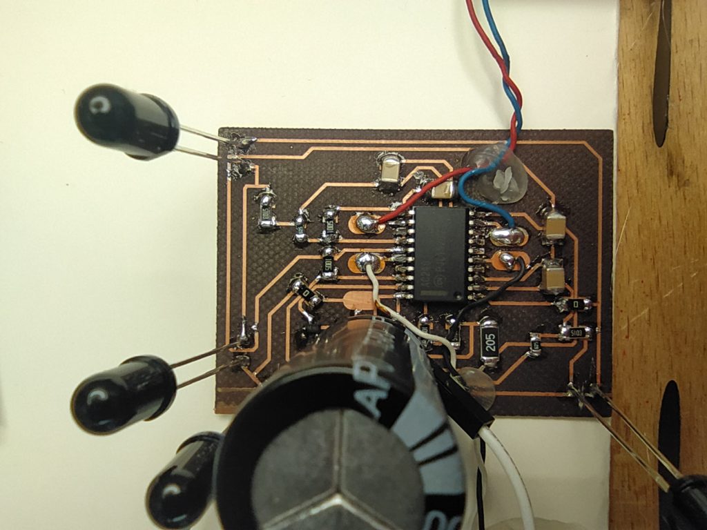
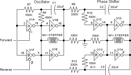
I have “air wired” this circuit after redrawing the circuit here:

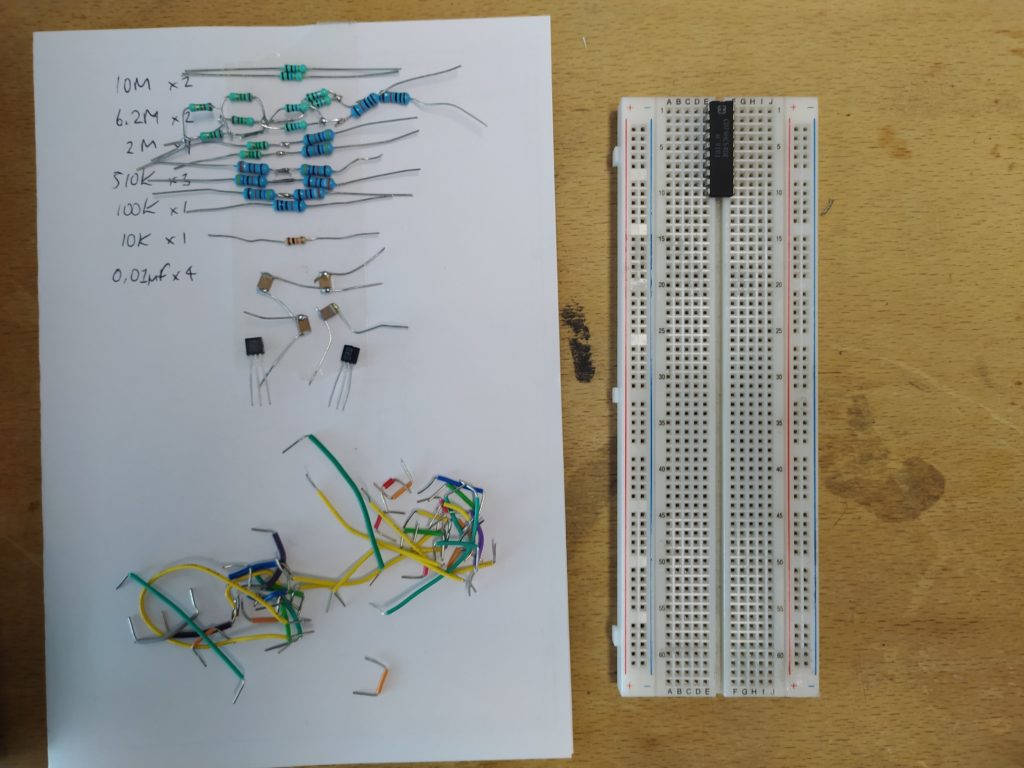
Here is the play by play of the assembly:


Here is how I glued the solar head to the post:

And here is another circuit which claims to do the same thing but which I failed to make work:

*********
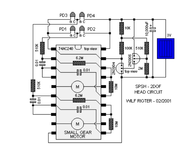
Making a version 2 following this schematic in SMD version. The goal is to replace the expensive and tech overkill 2DOF sunhead using LTC3105 and atmega developed on this page (https://www.marrs.io/fab-15-part-vii/). This comes with one caveat, I can’t use the cool stepper motor linear actuators I am collecting from CD/DVD drives… I have opened up 15 of these drives and only one came with a DC motor powered laser raft, and it was an ugly plastic mechanism. The other option is for me to design such a linear rail from scratch 3D printing the gears but then I lose the tech recyling angle and add considerable engineering challenge. The benefit is that it costs very little and is a simpler more minimal analog electronics solution. It could work for this design:
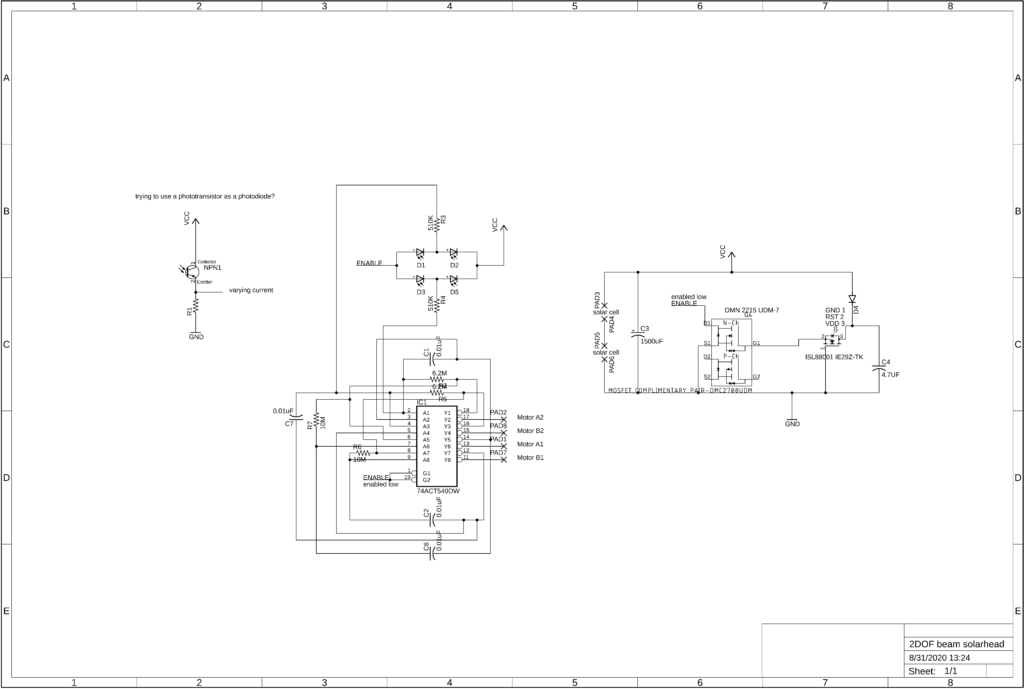
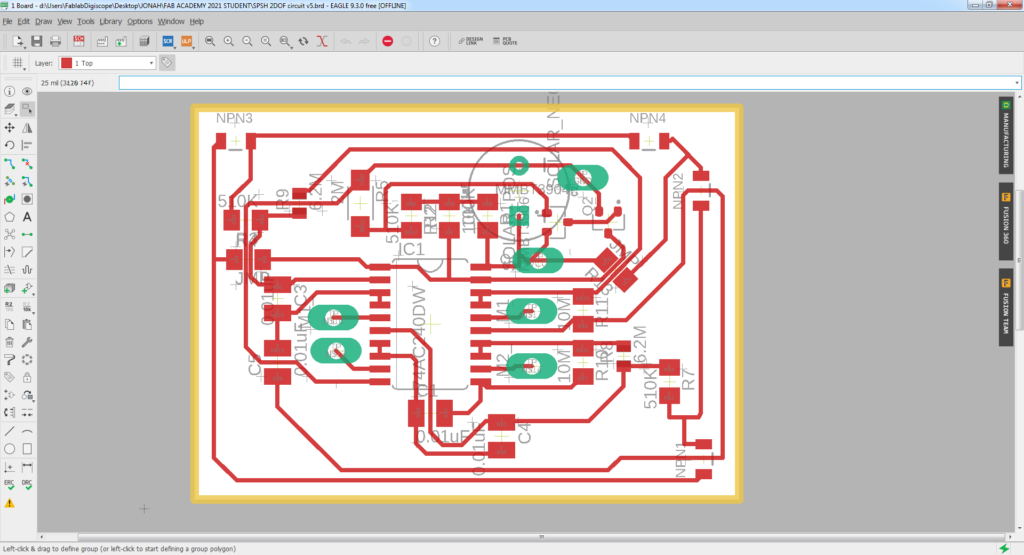
Here is the SPSH 2DOF circuit:
The different between photodiodes and phototransistors: https://circuitglobe.com/difference-between-photodiode-and-phototransistor.html#:~:text=One%20of%20the%20major%20difference,conversion%20of%20light%20into%20current.
Photodiodes appear to be rare, at least in the lab. Could something like the following turn a phototransistor into a photodiode? By changing the value of R1 you could change the degree of current change?
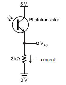
I could also just buy some photodiodes from Hackspark in Paris, though I would love to make this entirely SMD.
The challenge I want to set myself is to make an SMD version of this circuit. I have 74*540s in SMD, and I plan to build on the business card version of the 1381 solarengine which I’ve built here (https://www.marrs.io/solar-business-cards/). Rewiring the 540 based on the 240s in the original schematics but integrating the SMD solarengine is a possible stumbling block. I am working with the understanding that the solarengine essentially enables the buffer oscillators (instead of powering a motor ), by connecting the enables to low.
I’m not sure how easy the wiring is going to be on a single-sided board however…
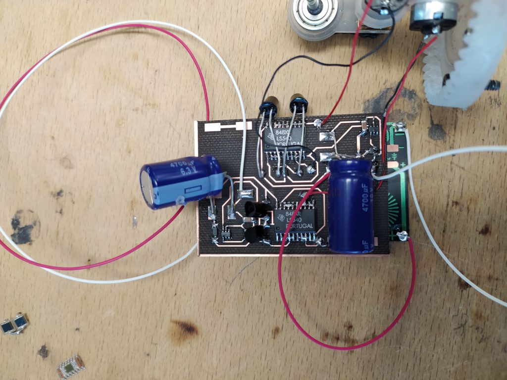
It turned out to be not too hard, the main issue was not having 10M and 6.2M resistors and having to make them from 1M resistors…As a result the board is larger than I would like (50mmx65mm approx.).
Here’s the completed board:
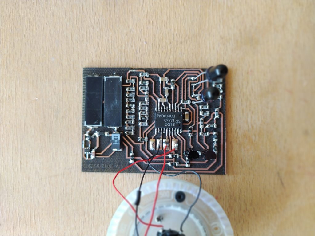
It’s not currently working, I added a higher power solar cell and a higher capacity cap. The cap is charging and the enable is high (oh wait it should be LOW! This must be the purpose of those extra resistors in the solar engine portion of the circuit. However it still doesn’t work when I pull the enable low artificially…) for the octal buffer but no power is arriving at the motors. So I’m thinking the issue is with the inverting oscillator parts of the circuit.
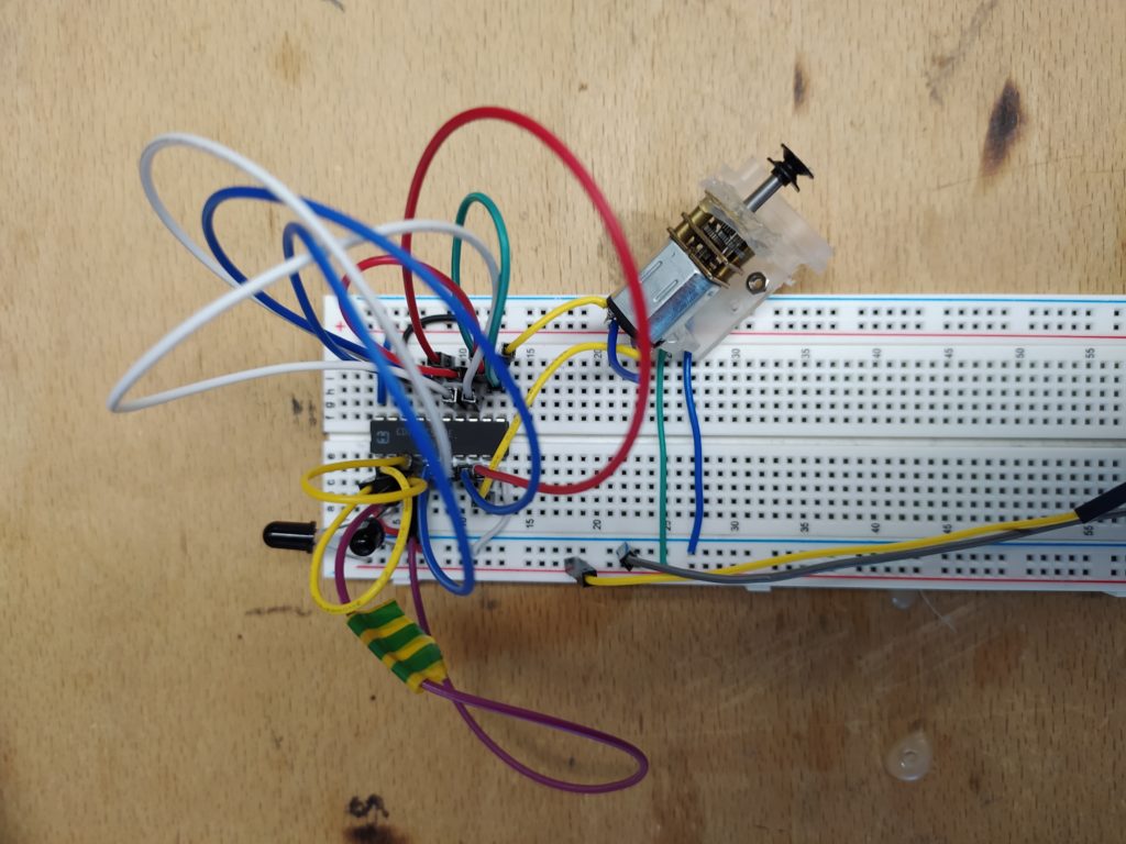
I removed the SMD solar engine and copied the schematic closely, but still no luck. I’m guessing there is an error or short on my board. I am going to try to breadboard this circuit to see if I have more luck.
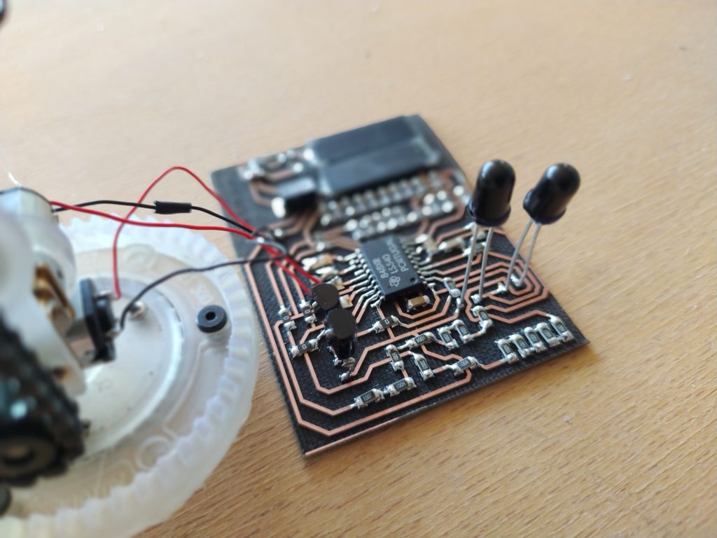
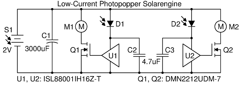
It may be simpler to make this circuit twice (from https://www.fetchmodus.org/projects/beam/photopopper/) as I already have everything I need. The circuit is straight forward and there is no analog business:
I just confirmed, the circuit can power the DC gearmotors I’m using well, even with the 1500uF cap. The package of MOSFETs I have comes in doubles so at least that is efficient. It doesn’t look great but my focus right now is the finalize the circuit so I can focus on the design of the sun seeker.
Here is the schematic:
After making this didn’t realize that it is for FOUR motors, i.e. there are not two motors which change direction…I tried wiring up the same motor for both and it doesn’t work of course because it’s not an H-bridge.
Here is another option, it would involve 2X this bare bones sun seeker, replacing the 240 with the 540 and the 1381 solar engine with the SMD version I am working with. From http://grant.solarbotics.net/Circuits.htm :
Ok this circuit is dead easy and works reliably so far. It has very few parts also! (Something I didn’t notice last test – it requires at least 4V to operate with these DC gearmotors…I also just tested and LEDs appear to be able to replace photodiodes no problem on the power supply powered breadboard version!)
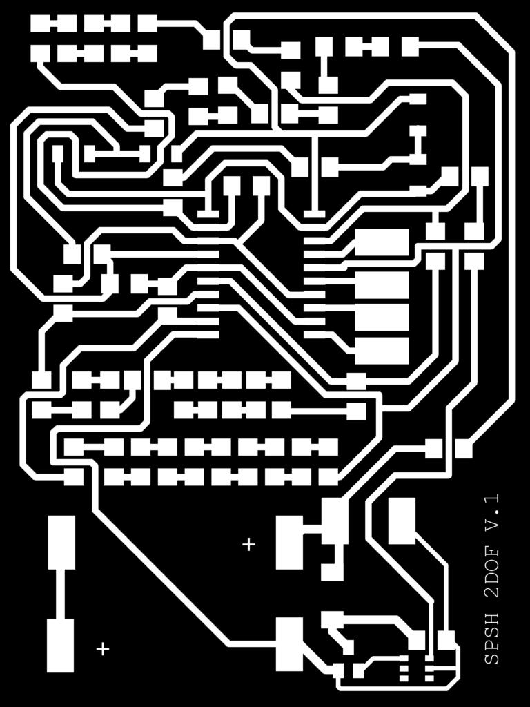
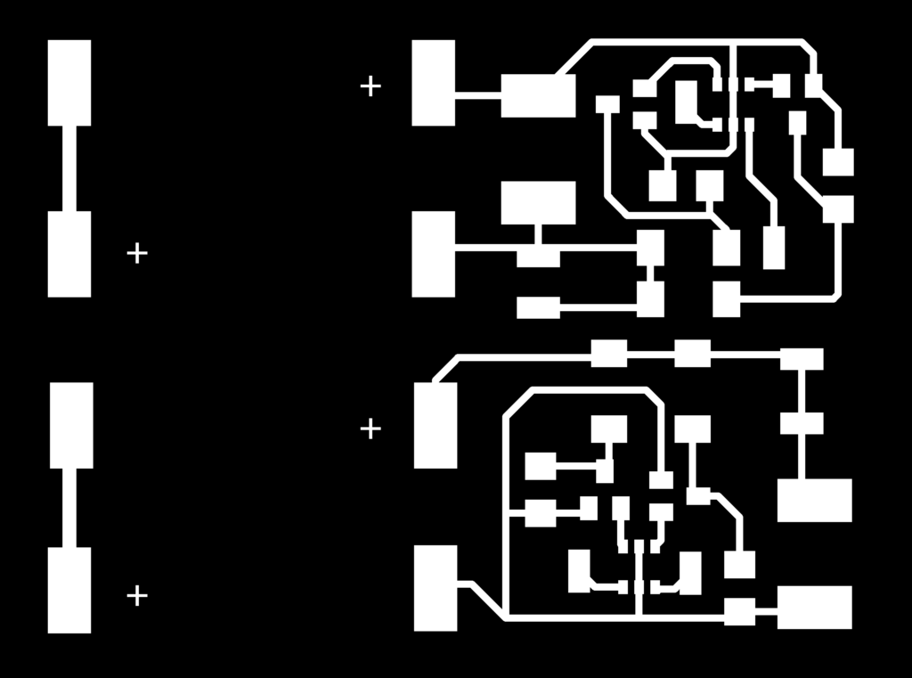
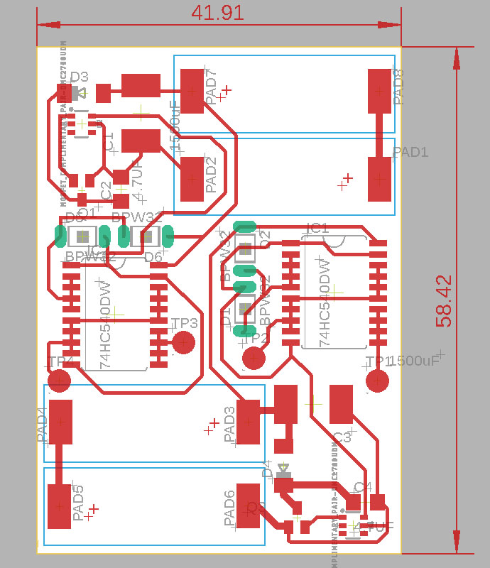
Here’s the SMD version ready to cut and prototype:
Unfortunately I need probably a larger capacitor and or more solar panels to make this setup work. With the 4700uF and the 6V solar cell everything works great, with either smaller caps or smaller cells there is some movement but very little. In his circuit he uses a 3.4V solar panel and a 3300uF cap so it may be possible to reduce these.
I’ve come to the realization that the SMD version of the miller engine I am working with doesn’t seem to vibe well with the head seeking circuits. I have been behaving like they are interchangeable but they may not be.
I went back to the breadboard version and included his miller engine. Everything works if you use a super light dc gearmotor (in white) but the gearmotors I am using aren’t happy with the voltage it would appear (so I need a higher 1381 flavor – like G instead of E). So I think this explains why the PCB I made didn’t work. (I tried unplugging the 1381 trigger pin and triggering the 2222 myself once the voltage maxed at 6V and alternating between putting each photodiode in darkness and it gives it a good spin. So I think it is indeed related to the top voltage – motor combination.)
*EDIT*
I have since tried adding a voltage divider to the sensor pin of the 1381 to effectively change the trigger voltage. With this technique it’s possible to make the circuit work with the small metal gearmotors if the voltage trigger is set around 4V+. This means that I could make a simple sunseeking circuit using 2x barebones and metal gear motors + prints!
I’m testing if this could work with modified Servo motors at the moment as well but so far no luck.
As for the issue with running those nice steppers with lead screws, it looks like it’s possible to buy DC gearmotors with leadscrews:

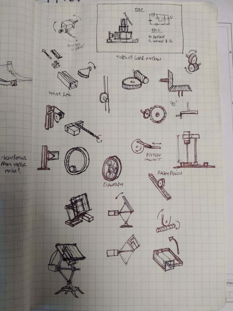
In parallel I am sketching some other ideas:
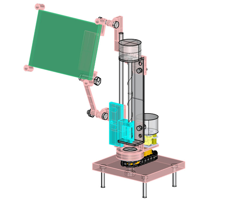
This is a double stepper version of a previous prototype. And here are some sketches of mechanisms I’d like to try out:

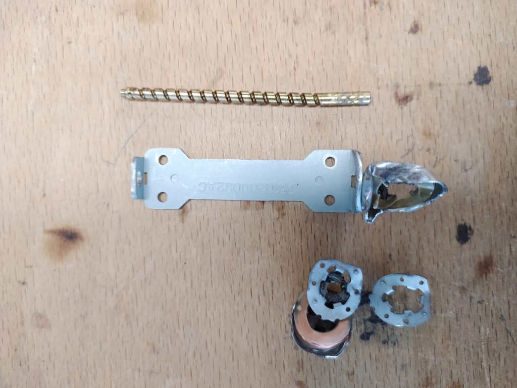
Attempt to convert a DC gear motor into linear actuator not starting smoothly…
This works nicely – except! – the black LED-style photodiode packages work best and the circuit only works with super tiny DC gear motors…This despite increasing the solar panels from 3V to 6V and it having a capacitance of almost 100,000uF. I don’t know what part of the circuit controls the trigger but this could be something to fiddle with potentially? (See documentation here: http://wilf.solarbotics.net/PSH/heads101.html ). It works super well with those inexpensive 2V garden lamp solar panels!!
Covering one photodiode at a time changes the direction. It’s quite efficient.
There is another BEAM related circuit to possibly check out…to drive stepper motors! From http://www.redrok.com/beamcircuits.htm
![]()
There is also this from http://solarbotics.net/library/circuits/driver_stepper_beamstep.html :
I would need to make this twice however, in order to have 2DOF and therefore have two solarengines which is not ideal.
Here is the almost finished uchip version of the circuit with 10 solar cells:
Quick look at cost of the entire thing:
Micro DC metal gearmotors – $14-17 !! (cf with Micro Stepper gearmotor – $5, solarbotics mini motors from $4.50-$9.25, and FREE found motors)
McMaster Carr sprockets – 4$/piece, roller chain $20/foot !
Fancy Solar Cells – $2 x 10 = $20 !! (cf with Solarbotics 22×24 $4.50, 22×33 $6.50, 33×37 – $8, and CHEAP lawn latern panels)
LTC3105 – $5.70 ! (but $3.25 if buy >25)
Supercap – $2-$4
DRV8833 – $1.25
Clearly recycling old motors and hardware is cost effective, as is finding a cheaper solar panel (taking one from a lawn latern if it’s powerful enough). Avoiding the need for the LTC saves a bit too but not as much as I originally thought. At bulk the electronics is negligeable and if the parts are all recycled it becomes relatively inexpensive. That said, the cheapest by far is found hardware and solar panel plus a BEAM style 2DOF sun seeker that would come in under $10 easily (especially because the circuit works super well with the garden lamp solar panels at 2V).
****
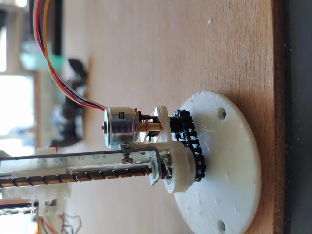
I haven’t got the stepper drivers working yet on the board. The 3D print had to be made out of a different material – so the offsets were not perfect. Some parts didn’t survive the printing and assembly as they were too fine also. I also didn’t realize that I have another identical linear actuator but not an identical threaded sliding block.
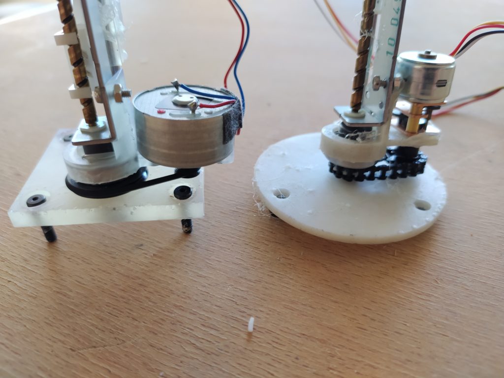
The two base options side by side:
I am starting to think this project is a little too ambitious! Perhaps a single axis machine, or something with a simple circuit.
****
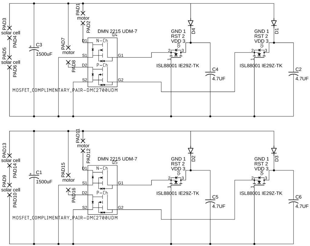
I tried the SPSH 2DOF again in SMD:
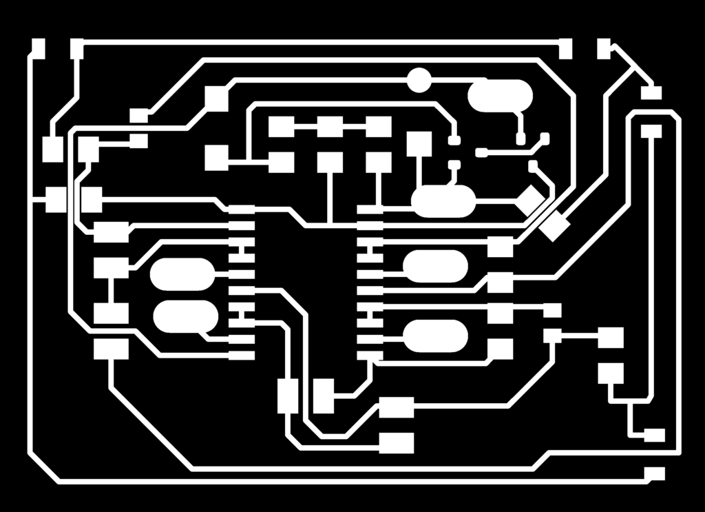
And here’s the circuit for testing: