Here is the schematic for noise (Quantum Random Number Generators – Scientific Figure on ResearchGate. Available from: https://www.researchgate.net/figure/Conceptual-representation-of-a-typical-noise-based-random-number-generator-The-voltage_fig6_301899096 [accessed 14 Oct 2024])

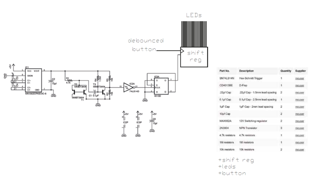
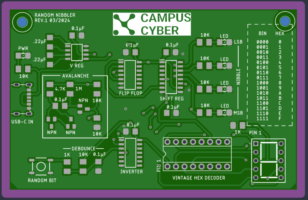
Made a random nibbler board based on this circuit :
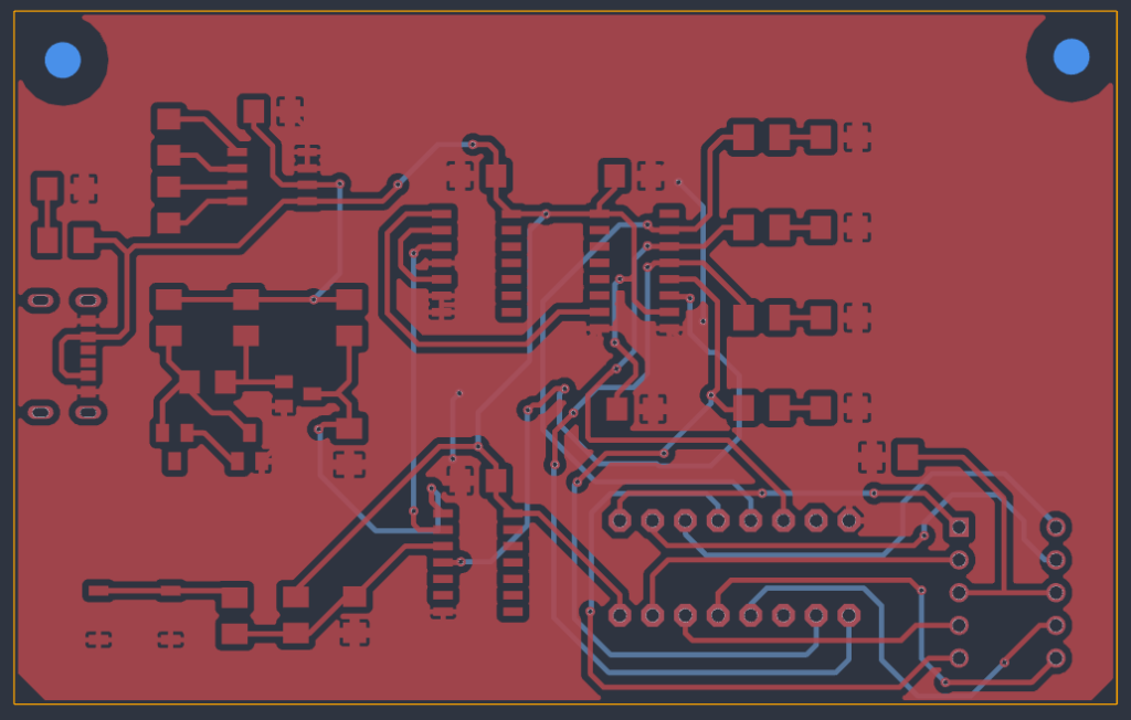
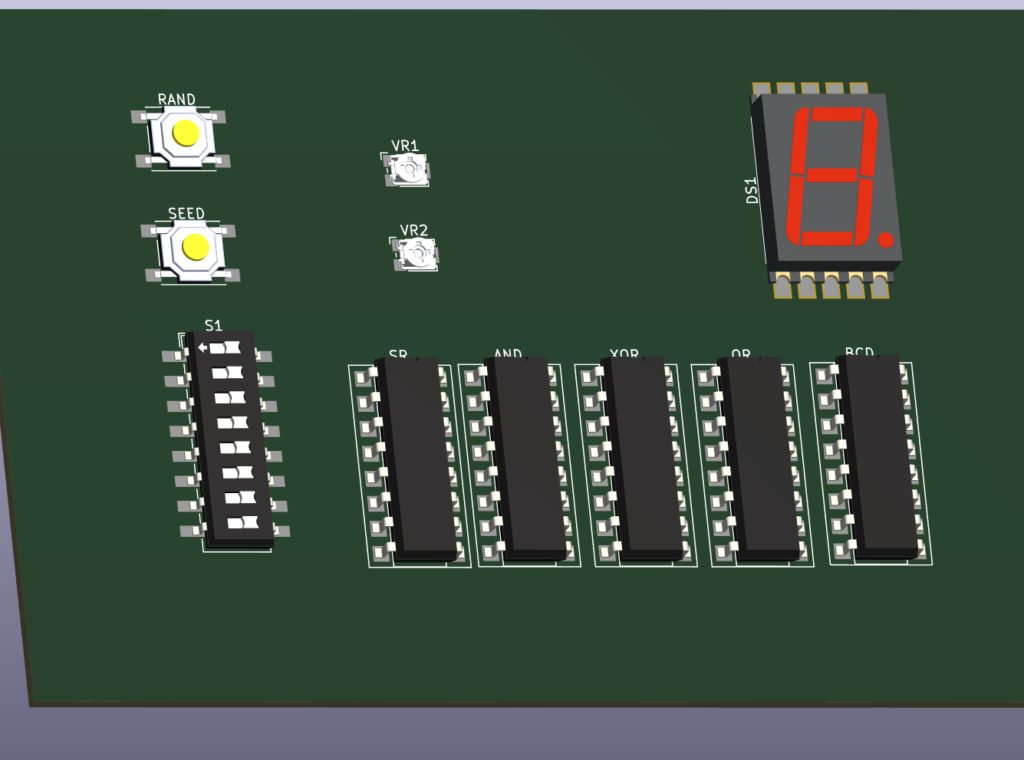
Here is the board sent to Aisler :
Here assembled :
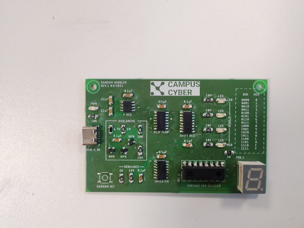
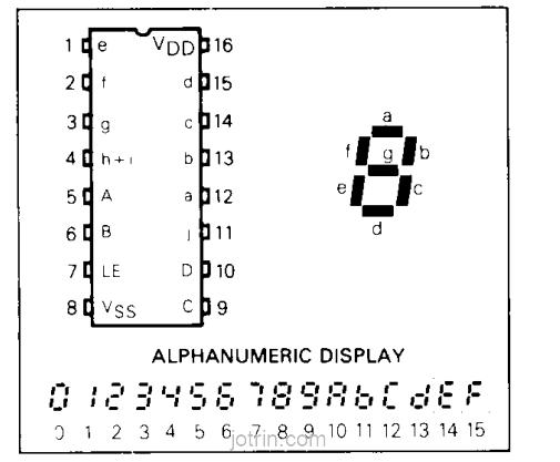
This is the special hex decoder chip we ordered from ebay :
So far I’ve got something around 200mV of noise. I’ve tried to place that smack in the middle of the 2.5V CMOS level but it remains stable and doesn’t flick back and forth.
I’ve learned that there are challenges with hardware noise, they are sensitive to power supply ripples and to neighbouring sources of electromagnetic radiation.
*****
From pp 558 and starting at 974 AoE
Digital noise with XNORs and big shift registers (64 bits and 8 bits) several bit positions of which that are fed back (called “taps” ) from to the inputs, then low pass filtered and amplified. A register with n bits goes through 2^n -1 states before repeating. It must be shifted higher than the frequency you sample the noise from.
https://en.wikipedia.org/wiki/Linear-feedback_shift_register
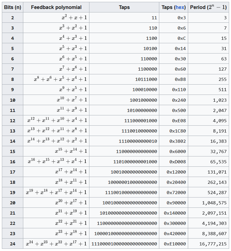
The feedback polynomial is determined by the taps chosen (the output is pin 16) :
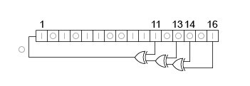

(1 is because x^0 = 1)
How cool would it be to let people pick the seed, change the taps and the total number of bits operating in the register, and the clocking and sampling frequencies, then to represent the noise on a 2D black and white plane !
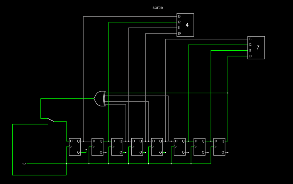
Here is the circuit built in Falstad here :
https://tinyurl.com/2ye8zb9f
https://tinyurl.com/2y88tftz
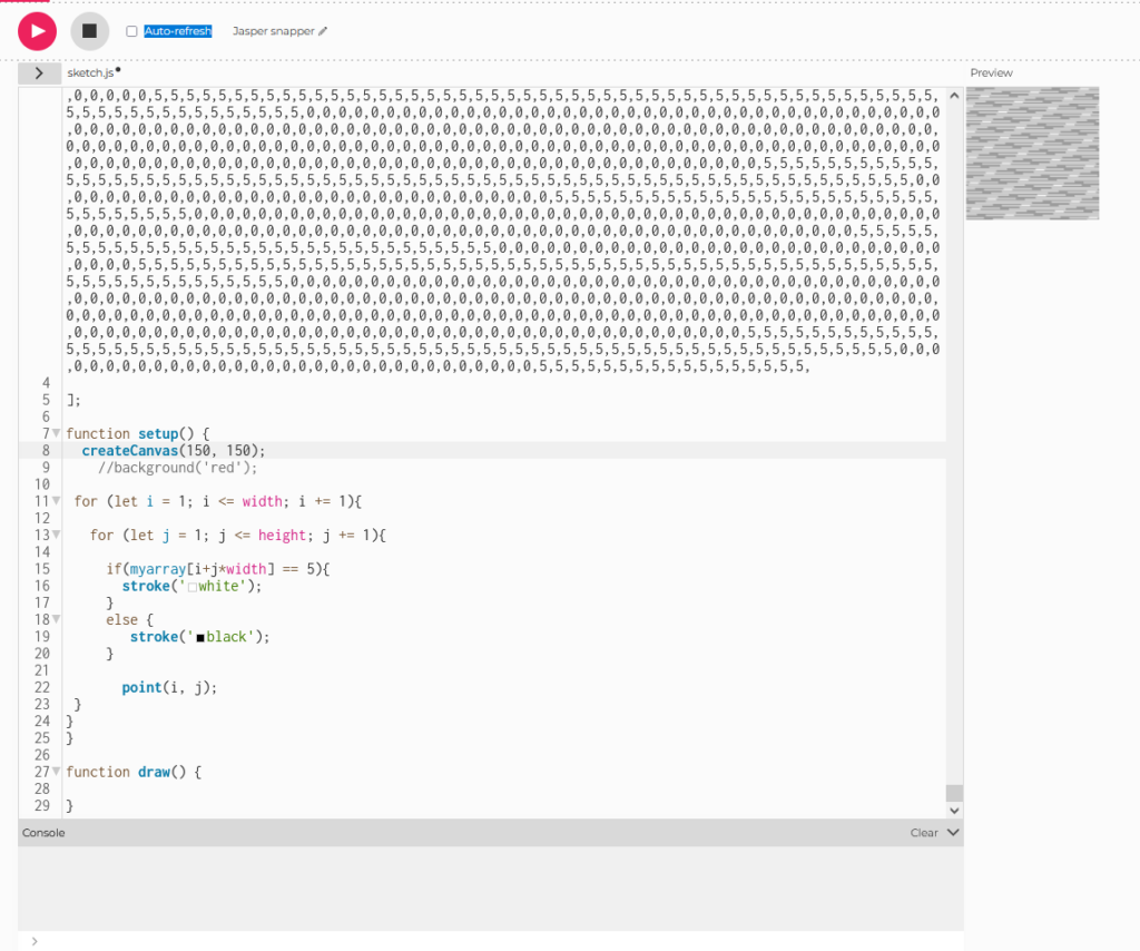
I am then exporting the output into a text file and visualizing it with Processing (after using Notepad++ find and replace to add commas between the values):
...
function setup() {

  createCanvas(200, 1000);

 for (let i = 1; i <= width; i += 1){
   for (let j = 1; j <= height; j += 1){
     if(myarray2[i+j*width] == 5){
       stroke('white');
     }
     else {
        stroke('black');
     }
       point(i, j);
 }
}
}
*********
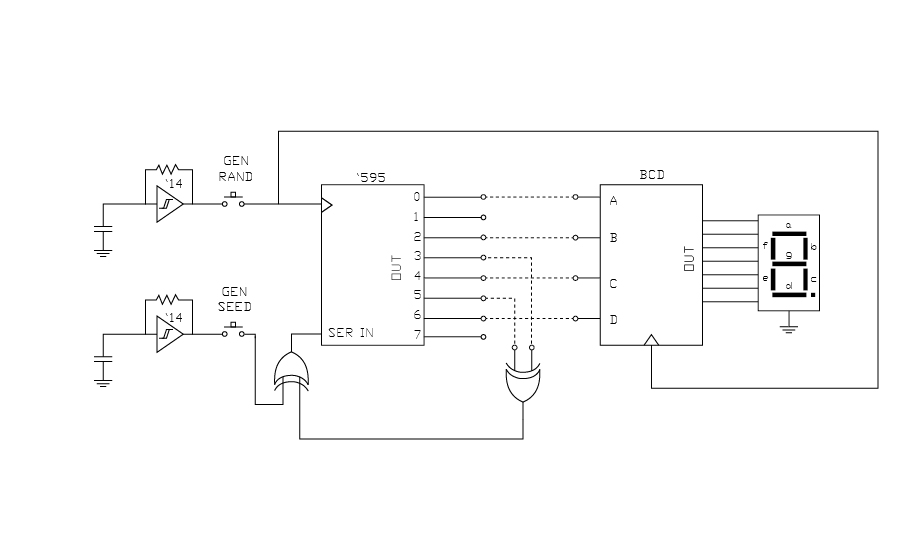
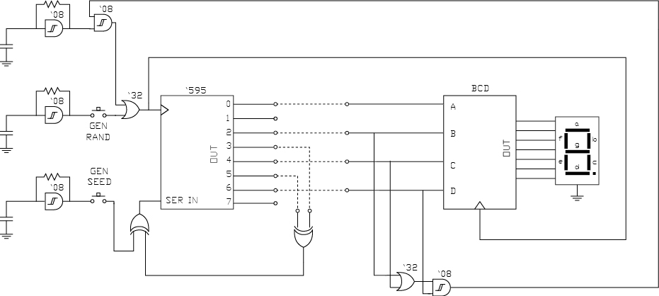
I should for next time have a schematic of the entire circuit and not just a tinkercad image :
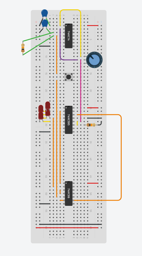
Basically two oscillators get fed into an XOR, the output of which is fed as the SERIAL IN for the 595 through another XOR which also takes feedback in from shift register taps. The second oscillator acts as the clock for the 595.
Here are some slides from the presentation :

**************
Check out this really random :
******
Other ideas (https://www.mdpi.com/2410-387X/7/2/26) seem to involve multiple ring oscillators :

Here is another article (https://www.mdpi.com/1099-4300/23/9/1168) trying to describe the random using this technique :

 | Alorium Technology")
********
Vintage hex decoder doesn’t work…
This works though and lets people reconfigure their circuit :
The 8 bit shift register could be replaced with a 16 or more bit register.
******
I’m replacing the non-working hex decoder with a standard BCD to Decimal decoder 74HC42 but then I have the issue of having 4 bits which describe more than 9 chars.
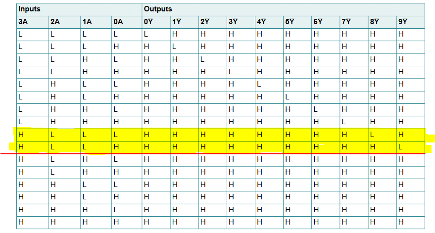
This means that 6/16 of the time there will be no number displayed. I basically need to be able to tell when there is no display so I can keep generating random numbers, while maintaining the same odds for all numbers.
Perhaps I can add logic to detect when D is H while ABC are L (8), and another for when D and A are high and B and C are low (9). I have NOT and XOR gates left over so this should be possible ?
I can do it with an OR and AND using BCD inputs.
******
Also learning KiCAD. Everything very easy so far except for adding external parts.
Preferences > Configurer les Librarie de Symboles, then hit the plus to add a new library (kicad_sym is the file extension).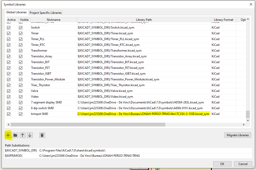
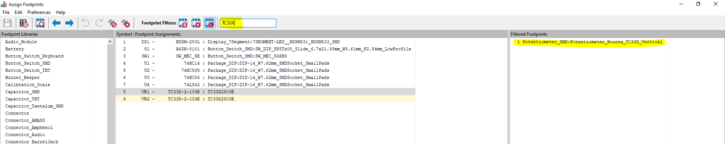
Then to add the footprint assignment tool : Tools > Assign Footprints using the search bar at the top and double clicking on the part on the right.
To add a 3D package, double click on the origin of the component in board mode and select the 3D tab, then change the orientation :
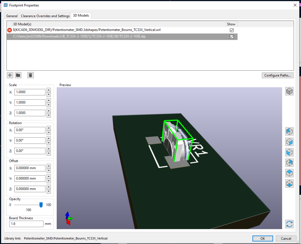
F3 or View > 3D view :
****
I have a new version of the circuit that gets rid of NOT gates and adds the ability to keep generating numbers until it gets a valid number.
I wonder if I can eliminate the two buttons. Also, how exactly do the DIP switches work here ?