After failing to do various “simple” things in verilog, I’m doing a little refresher course. Resources :
- https://hackaday.com/series_of_posts/williams-icestick-tutorial/
- https://www.doulos.com/knowhow/verilog_designers_guide/
- https://vol.verilog.com/
//VERILOG CODING PRACTICES //verilog is case sensitive ! reg THIS; // not the same as this ! reg this; //to repeat : {repeat_count{}} vec[1:20] = {4{5'b10110}}; ********** // this is better than just [23:0] for readability : parameter buswidth = 24; input [buswidth-1:0] bus; //this is better than just 47:0 for readability : reg [8*6:1] string6; *********** //scalars (single bit vs vectors which are multi-bit) can have the following values: 0 - logic zero (false) 1 - logic one (true) x - unknown value z - high-impedance value // therefore an equality test can return unknown if one of the operands is x or z ! if (expression) is evaluated : 0 false 1 true x false z false//nets receive signal values //net or register port expressions send values //regs need initial conditions, wires need NOT to have initial conditions assigned. //keep in mind if you're making combinational or sequential logic ! ******* //legal assignments : lhs = rhs; lhs[bit] = rhs; lhs[partmsb:partlsb] = rhs; {lhs1, lhs2} = rhs; *********** //for a null operation use the semi-colon : if (control) ; else x = f(y); ******* //You can give names to binary combinations : `define A 3'b001 `define B 3'b010 `define C 3'b100 initial state = `A; ******** //You can deassign : else if (!preset) assign q = 1; else deassign q; ********* // in simulation you can use the $random system function integer rand; rand = $random; ************* //don't do this : assign n1 = w1 + f(w2) + g(w3); //do this instead : assign t2 = f(w2); assign t3 = g(w3); assign n1 = w1 + t2 + t3; ************ //this : wire AB; assign AB = A & B; // can be written like this : wire AB = A & B; ************** //This creates an implicit sensitivity list that contains all the signals whose values are //read in the statements of the always block : always @(*) //Remember : To synthesize combinational logic using an always block, //ALL inputs to the design must appear in the sensitivity list. ******** // LATCHES // https://nandland.com/how-to-avoid-creating-a-latch/ //Latches are bad, they are combinational and not driven by a clock. If you use a clocked process //you avoid the possibility of unintentionally making a latch. //All combinational processes need to explicit assignments for every possibility. Don't leave a conditional test //that has only an if and no else to account for the other possible values.
// TEST BENCHES //for test benches use # to make things happen at certain times : x = 0; #10 x = x + 1; #20 x = x + 2; #30 x = x + 3; #20 x = x + 2; #10 x = x + 1; time: value of x : 0 0 10 1 30 3 60 6 80 8 90 9// for test bench clocks : always begin #period/2 clk = ~clk; end
// CLOCK BUFFERING

Do external clocks need buffering ? If so, is this how to buffer an external clock ?

SB_GB_IO gb_io1 (
.PACKAGE_PIN( clk ),
.GLOBAL_BUFFER_OUTPUT( gclk )
);

...or with extra params ?

SB_GB_IO gb_io1
( .PACKAGE_PIN(clk),
.OUTPUT_ENABLE(1'b1),
.GLOBAL_BUFFER_OUTPUT(gclk)
);
defparam gb_io1.PIN_TYPE = 6'b000001;
defparam gb_io1.PULLUP = 1'b0;
defparam gb_io1.NEG_TRIGGER = 1'b0;
defparam gb_io1.IO_STANDARD = "SB_LVCMOS";
// MEMORY
// to instantiate 1 bit memory :
reg membits [1023:0]; // 1024 1-bit registers
//You can't take a bit-select or part-select of a memory element.
//Thus, if you want to get the 3rd bit out of the 10th element of a memory,
//you need to do it in two steps:
reg [0:31] temp, mem[1:1024];
...
temp = mem[10];
bit = temp[3];
// RACE CONDITIONS
// This code produces a 'race condition' :

always @(posedge clock) always @(posedge clock)
dff1 = f(x); dff2 = dff1;

// it can be fixed with non-blocking assignments :

always @(posedge clock) always @(posedge clock)
dff1 <= f(x); dff2 <= dff1;

//CROSSING CLOCK DOMAINS

one solution is to double latch everything.
**********
I am systematically trying to figure out why I can’t take rpi input and redisplay it with the simple HDMI code.
I am starting by sending signals in a pass through way like this :
always @(posedge rpi_pixel_clock) begin

b_in_repeat <= b_in;

end
I get the same input signal but one clock later on the ‘scope so as expected.
`default_nettype none // disable implicit definitions by Verilog

module top(
input wire clk100, // replace with pixel clock of the rpi ? Slow to speed of rpi ?

input wire rpi_pixel_clock,

input wire b_in,
output reg b_in_repeat

);


reg r1_data = 0;
reg r2_data = 0;

always @(posedge rpi_pixel_clock) begin


r1_data <= b_in;
r2_data <= r1_data;

end

always @(posedge clk100) begin


b_in_repeat <= r2_data;

end

endmodule
Here’s a new code that at least kind of displays incoming data from the rpi :
`default_nettype none // disable implicit definitions by Verilog
//-----------------------------------------------------------------
// minimalDVID_encoder.vhd : A quick and dirty DVI-D implementation
//
// Author: Mike Field <hamster@snap.net.nz>
//
// DVI-D uses TMDS as the 'on the wire' protocol, where each 8-bit
// value is mapped to one or two 10-bit symbols, depending on how
// many 1s or 0s have been sent. This makes it a DC balanced protocol,
// as a correctly implemented stream will have (almost) an equal
// number of 1s and 0s.
//
// Because of this implementation quite complex. By restricting the
// symbols to a subset of eight symbols, all of which having have
// five ones (and therefore five zeros) this complexity drops away
// leaving a simple implementation. Combined with a DDR register to
// send the symbols the complexity is kept very low.
//-----------------------------------------------------------------

module top(

clk100, hdmi_p, hdmi_n, rpi_pixel_clock, b_in, rpi_DEN

);

input clk100;
output [3:0] hdmi_p;
output [3:0] hdmi_n;
input wire rpi_pixel_clock;
input wire b_in;
input wire rpi_DEN;

// For holding the outward bound TMDS symbols in the slow and fast domain
reg [9:0] c0_symbol; reg [9:0] c0_high_speed;
reg [9:0] c1_symbol; reg [9:0] c1_high_speed;
reg [9:0] c2_symbol; reg [9:0] c2_high_speed;
reg [9:0] clk_high_speed;

reg [1:0] c2_output_bits;
reg [1:0] c1_output_bits;
reg [1:0] c0_output_bits;
reg [1:0] clk_output_bits;

wire clk_x5;
reg [2:0] latch_high_speed = 3'b100; // Controlling the transfers into the high speed domain

wire vsync, hsync;
wire [1:0] syncs; // To glue the HSYNC and VSYNC into the control character
assign syncs = {vsync, hsync};

// video structure constants
parameter hpixels = 800; // horizontal pixels per line
parameter vlines = 525; // vertical lines per frame
parameter hpulse = 96; // hsync pulse length
parameter vpulse = 2; // vsync pulse length
parameter hbp = 144; // end of horizontal back porch (96 + 48)
parameter hfp = 784; // beginning of horizontal front porch (800 - 16)
parameter vbp = 35; // end of vertical back porch (2 + 33)
parameter vfp = 515; // beginning of vertical front porch (525 - 10)

// registers for storing the horizontal & vertical counters
reg [9:0] vc;
reg [9:0] hc;
// generate sync pulses (active high)
assign vsync = (vc < vpulse);
assign hsync = (hc < hpulse);

reg r1_data = 0;
reg r2_data = 0;

reg r3_data = 0;
reg r4_data = 0;

always @(posedge rpi_pixel_clock) begin

r1_data <= b_in;
r2_data <= r1_data;

r3_data <= rpi_DEN;
r4_data <= r3_data;

end


always @(posedge clk_x5) begin
//-------------------------------------------------------------
// Now take the 10-bit words and take it into the high-speed
// clock domain once every five cycles.
//
// Then send out two bits every clock cycle using DDR output
// registers.
//-------------------------------------------------------------
c0_output_bits <= c0_high_speed[1:0];
c1_output_bits <= c1_high_speed[1:0];
c2_output_bits <= c2_high_speed[1:0];
clk_output_bits <= clk_high_speed[1:0];
if (latch_high_speed[2]) begin // pixel clock 25MHz
c0_high_speed <= c0_symbol;
c1_high_speed <= c1_symbol;
c2_high_speed <= c2_symbol;
clk_high_speed <= 10'b0000011111;
latch_high_speed <= 3'b000;
if (hc < hpixels)
hc <= hc + 1;
else
begin
hc <= 0;
if (vc < vlines)
vc <= vc + 1;
else
vc <= 0;
end
end
else begin
c0_high_speed <= {2'b00, c0_high_speed[9:2]};
c1_high_speed <= {2'b00, c1_high_speed[9:2]};
c2_high_speed <= {2'b00, c2_high_speed[9:2]};
clk_high_speed <= {2'b00, clk_high_speed[9:2]};
latch_high_speed <= latch_high_speed + 1'b1;
end
end

always @(*) // display 100% saturation colourbars
begin
// first check if we're within vertical active video range
if (vc >= vbp && vc < vfp)
begin
// now display different colours every 80 pixels
// while we're within the active horizontal range
// -----------------
// display white bar
if (hc >= hbp && hc < hfp && r2_data == 1'b1 && r4_data == 1'b1 ) //
begin
c2_symbol = 10'b1011110000; // red
c1_symbol = 10'b1011110000; // green
c0_symbol = 10'b1011110000; // blue
end
// display black bar
else if (hc >= hbp && hc < hfp && r2_data == 1'b0 && r4_data == 1'b1)
begin
c2_symbol = 10'b0111110000; // red
c1_symbol = 10'b0111110000; // green
c0_symbol = 10'b0111110000; // blue
end
// display red bar
else if (hc >= hbp && hc < hfp && r2_data != 1'b0 && r2_data != 1'b1 && r4_data == 1'b1)// if r2_data == x or r2_data == z
begin
c2_symbol = 10'b1011110000; // red
c1_symbol = 10'b0111110000; // green
c0_symbol = 10'b0111110000; // blue
end
// we're outside active horizontal range
else
begin
c2_symbol = 10'b1101010100; // red
c1_symbol = 10'b1101010100; // green
//---------------------------------------------
// Channel 0 carries the blue pixels, and also
// includes the HSYNC and VSYNCs during
// the CTL (blanking) periods.
//---------------------------------------------
case (syncs)
2'b00 : c0_symbol = 10'b1101010100;
2'b01 : c0_symbol = 10'b0010101011;
2'b10 : c0_symbol = 10'b0101010100;
default : c0_symbol = 10'b1010101011;
endcase
end
end
// we're outside active vertical range
else
begin
c2_symbol = 10'b1101010100; // red
c1_symbol = 10'b1101010100; // green
//---------------------------------------------
// Channel 0 carries the blue pixels, and also
// includes the HSYNC and VSYNCs during
// the CTL (blanking) periods.
//---------------------------------------------
case (syncs)
2'b00 : c0_symbol = 10'b1101010100;
2'b01 : c0_symbol = 10'b0010101011;
2'b10 : c0_symbol = 10'b0101010100;
default : c0_symbol = 10'b1010101011;
endcase
end
end

// red N
defparam hdmin2.PIN_TYPE = 6'b010000;
defparam hdmin2.IO_STANDARD = "SB_LVCMOS";
SB_IO hdmin2 (
.PACKAGE_PIN (hdmi_n[2]),
.CLOCK_ENABLE (1'b1),
.OUTPUT_CLK (clk_x5),
.OUTPUT_ENABLE (1'b1),
.D_OUT_0 (~c2_output_bits[1]),
.D_OUT_1 (~c2_output_bits[0])
);

// red P
defparam hdmip2.PIN_TYPE = 6'b010000;
defparam hdmip2.IO_STANDARD = "SB_LVCMOS";
SB_IO hdmip2 (
.PACKAGE_PIN (hdmi_p[2]),
.CLOCK_ENABLE (1'b1),
.OUTPUT_CLK (clk_x5),
.OUTPUT_ENABLE (1'b1),
.D_OUT_0 (c2_output_bits[1]),
.D_OUT_1 (c2_output_bits[0])
);

// green N
defparam hdmin1.PIN_TYPE = 6'b010000;
defparam hdmin1.IO_STANDARD = "SB_LVCMOS";
SB_IO hdmin1 (
.PACKAGE_PIN (hdmi_n[1]),
.CLOCK_ENABLE (1'b1),
.OUTPUT_CLK (clk_x5),
.OUTPUT_ENABLE (1'b1),
.D_OUT_0 (~c1_output_bits[1]),
.D_OUT_1 (~c1_output_bits[0])
);

// green P
defparam hdmip1.PIN_TYPE = 6'b010000;
defparam hdmip1.IO_STANDARD = "SB_LVCMOS";
SB_IO hdmip1 (
.PACKAGE_PIN (hdmi_p[1]),
.CLOCK_ENABLE (1'b1),
.OUTPUT_CLK (clk_x5),
.OUTPUT_ENABLE (1'b1),
.D_OUT_0 (c1_output_bits[1]),
.D_OUT_1 (c1_output_bits[0])
);


// blue N
defparam hdmin0.PIN_TYPE = 6'b010000;
defparam hdmin0.IO_STANDARD = "SB_LVCMOS";
SB_IO hdmin0 (
.PACKAGE_PIN (hdmi_n[0]),
.CLOCK_ENABLE (1'b1),
.OUTPUT_CLK (clk_x5),
.OUTPUT_ENABLE (1'b1),
.D_OUT_0 (~c0_output_bits[1]),
.D_OUT_1 (~c0_output_bits[0])
);

// blue P
defparam hdmip0.PIN_TYPE = 6'b010000;
defparam hdmip0.IO_STANDARD = "SB_LVCMOS";
SB_IO hdmip0 (
.PACKAGE_PIN (hdmi_p[0]),
.CLOCK_ENABLE (1'b1),
.OUTPUT_CLK (clk_x5),
.OUTPUT_ENABLE (1'b1),
.D_OUT_0 (c0_output_bits[1]),
.D_OUT_1 (c0_output_bits[0])
);

// clock N
defparam hdmin3.PIN_TYPE = 6'b010000;
defparam hdmin3.IO_STANDARD = "SB_LVCMOS";
SB_IO hdmin3 (
.PACKAGE_PIN (hdmi_n[3]),
.CLOCK_ENABLE (1'b1),
.OUTPUT_CLK (clk_x5),
.OUTPUT_ENABLE (1'b1),
.D_OUT_0 (~clk_output_bits[1]),
.D_OUT_1 (~clk_output_bits[0])
);


// clock P
defparam hdmip3.PIN_TYPE = 6'b010000;
defparam hdmip3.IO_STANDARD = "SB_LVCMOS";
SB_IO hdmip3 (
.PACKAGE_PIN (hdmi_p[3]),
.CLOCK_ENABLE (1'b1),
.OUTPUT_CLK (clk_x5),
.OUTPUT_ENABLE (1'b1),
.D_OUT_0 (clk_output_bits[1]),
.D_OUT_1 (clk_output_bits[0])
);
// D_OUT_0 and D_OUT_1 swapped?
// https://github.com/YosysHQ/yosys/issues/330


SB_PLL40_PAD #(
.FEEDBACK_PATH ("SIMPLE"),
.DIVR (4'b0000),
.DIVF (7'b0001001),
.DIVQ (3'b011),
.FILTER_RANGE (3'b101)
) uut (
.RESETB (1'b1),
.BYPASS (1'b0),
.PACKAGEPIN (clk100),
.PLLOUTGLOBAL (clk_x5) // DVI clock 125MHz
);

endmodule
I am trying taking every single rpi input signal, buffering it, and then replacing the sync counters with these inputs :
I am guessing that it is successfully sending the video information but that 720×720 is not an acceptable HDMI format ?
`default_nettype none // disable implicit definitions by Verilog
//-----------------------------------------------------------------
// minimalDVID_encoder.vhd : A quick and dirty DVI-D implementation
//
// Author: Mike Field <hamster@snap.net.nz>
//
// DVI-D uses TMDS as the 'on the wire' protocol, where each 8-bit
// value is mapped to one or two 10-bit symbols, depending on how
// many 1s or 0s have been sent. This makes it a DC balanced protocol,
// as a correctly implemented stream will have (almost) an equal
// number of 1s and 0s.
//
// Because of this implementation quite complex. By restricting the
// symbols to a subset of eight symbols, all of which having have
// five ones (and therefore five zeros) this complexity drops away
// leaving a simple implementation. Combined with a DDR register to
// send the symbols the complexity is kept very low.
//-----------------------------------------------------------------

module top(

clk100, hdmi_p, hdmi_n, rpi_pixel_clock, b_in, rpi_DEN, rpi_vsync

);

input clk100;
output [3:0] hdmi_p;
output [3:0] hdmi_n;
input wire rpi_pixel_clock;
input wire b_in;
input wire rpi_DEN;
input wire rpi_vsync;

/*

pcf :

set_io rpi_pixel_clock 61
set_io b_in 62
set_io rpi_DEN 52

set_io rpi_vsync 63

*/

// For holding the outward bound TMDS symbols in the slow and fast domain
reg [9:0] c0_symbol; reg [9:0] c0_high_speed;
reg [9:0] c1_symbol; reg [9:0] c1_high_speed;
reg [9:0] c2_symbol; reg [9:0] c2_high_speed;
reg [9:0] clk_high_speed;

reg [1:0] c2_output_bits;
reg [1:0] c1_output_bits;
reg [1:0] c0_output_bits;
reg [1:0] clk_output_bits;

wire clk_x5;
reg [2:0] latch_high_speed = 3'b100; // Controlling the transfers into the high speed domain

wire vsync, hsync;
wire [1:0] syncs; // To glue the HSYNC and VSYNC into the control character
assign syncs = {vsync, hsync};

// video structure constants
parameter hpixels = 800; // horizontal pixels per line
parameter vlines = 525; // vertical lines per frame
parameter hpulse = 96; // hsync pulse length
parameter vpulse = 2; // vsync pulse length
parameter hbp = 144; // end of horizontal back porch (96 + 48)
parameter hfp = 784; // beginning of horizontal front porch (800 - 16)
parameter vbp = 35; // end of vertical back porch (2 + 33)
parameter vfp = 515; // beginning of vertical front porch (525 - 10)

// registers for storing the horizontal & vertical counters
reg [9:0] vc;
reg [9:0] hc;
// generate sync pulses (active high)
assign vsync = (vc < vpulse);
assign hsync = (hc < hpulse);

reg r1_data = 0;
reg r2_data = 0;

reg r3_data = 0;
reg r4_data = 0;

reg r7_data = 0;
reg r8_data = 0;

always @(posedge rpi_pixel_clock) begin // shouod be clk_x5 ?

r1_data <= b_in;
r2_data <= r1_data;

r3_data <= rpi_DEN;
r4_data <= r3_data;

r7_data <= rpi_vsync;
r8_data <= r7_data;

end


always @(posedge clk_x5) begin
//-------------------------------------------------------------
// Now take the 10-bit words and take it into the high-speed
// clock domain once every five cycles.
//
// Then send out two bits every clock cycle using DDR output
// registers.
//-------------------------------------------------------------
c0_output_bits <= c0_high_speed[1:0];
c1_output_bits <= c1_high_speed[1:0];
c2_output_bits <= c2_high_speed[1:0];
clk_output_bits <= clk_high_speed[1:0];
if (latch_high_speed[2]) begin // pixel clock 25MHz
c0_high_speed <= c0_symbol;
c1_high_speed <= c1_symbol;
c2_high_speed <= c2_symbol;
clk_high_speed <= 10'b0000011111;
latch_high_speed <= 3'b000;
if (hc < hpixels)
hc <= hc + 1;
else
begin
hc <= 0;
if (vc < vlines)
vc <= vc + 1;
else
vc <= 0;
end
end
else begin
c0_high_speed <= {2'b00, c0_high_speed[9:2]};
c1_high_speed <= {2'b00, c1_high_speed[9:2]};
c2_high_speed <= {2'b00, c2_high_speed[9:2]};
clk_high_speed <= {2'b00, clk_high_speed[9:2]};
latch_high_speed <= latch_high_speed + 1'b1;
end
end

always @(*) // display 100% saturation colourbars
begin
// first check if we're within vertical active video range
if (r8_data)
begin
// now display different colours every 80 pixels
// while we're within the active horizontal range
// -----------------
// display white bar
if (r2_data == 1'b1 && r4_data == 1'b1 ) //
begin
c2_symbol = 10'b1011110000; // red
c1_symbol = 10'b1011110000; // green
c0_symbol = 10'b1011110000; // blue
end
// display black bar
else if (r2_data == 1'b0 && r4_data == 1'b1)
begin
c2_symbol = 10'b0111110000; // red
c1_symbol = 10'b0111110000; // green
c0_symbol = 10'b0111110000; // blue
end
// we're outside active horizontal range
else
begin
c2_symbol = 10'b1101010100; // red
c1_symbol = 10'b1101010100; // green
//---------------------------------------------
// Channel 0 carries the blue pixels, and also
// includes the HSYNC and VSYNCs during
// the CTL (blanking) periods.
//---------------------------------------------
case (syncs)
2'b00 : c0_symbol = 10'b1101010100;
2'b01 : c0_symbol = 10'b0010101011;
2'b10 : c0_symbol = 10'b0101010100;
default : c0_symbol = 10'b1010101011;
endcase
end
end
// we're outside active vertical range
else
begin
c2_symbol = 10'b1101010100; // red
c1_symbol = 10'b1101010100; // green
//---------------------------------------------
// Channel 0 carries the blue pixels, and also
// includes the HSYNC and VSYNCs during
// the CTL (blanking) periods.
//---------------------------------------------
case (syncs)
2'b00 : c0_symbol = 10'b1101010100;
2'b01 : c0_symbol = 10'b0010101011;
2'b10 : c0_symbol = 10'b0101010100;
default : c0_symbol = 10'b1010101011;
endcase
end
end

// red N
defparam hdmin2.PIN_TYPE = 6'b010000;
defparam hdmin2.IO_STANDARD = "SB_LVCMOS";
SB_IO hdmin2 (
.PACKAGE_PIN (hdmi_n[2]),
.CLOCK_ENABLE (1'b1),
.OUTPUT_CLK (clk_x5),
.OUTPUT_ENABLE (1'b1),
.D_OUT_0 (~c2_output_bits[1]),
.D_OUT_1 (~c2_output_bits[0])
);

// red P
defparam hdmip2.PIN_TYPE = 6'b010000;
defparam hdmip2.IO_STANDARD = "SB_LVCMOS";
SB_IO hdmip2 (
.PACKAGE_PIN (hdmi_p[2]),
.CLOCK_ENABLE (1'b1),
.OUTPUT_CLK (clk_x5),
.OUTPUT_ENABLE (1'b1),
.D_OUT_0 (c2_output_bits[1]),
.D_OUT_1 (c2_output_bits[0])
);

// green N
defparam hdmin1.PIN_TYPE = 6'b010000;
defparam hdmin1.IO_STANDARD = "SB_LVCMOS";
SB_IO hdmin1 (
.PACKAGE_PIN (hdmi_n[1]),
.CLOCK_ENABLE (1'b1),
.OUTPUT_CLK (clk_x5),
.OUTPUT_ENABLE (1'b1),
.D_OUT_0 (~c1_output_bits[1]),
.D_OUT_1 (~c1_output_bits[0])
);

// green P
defparam hdmip1.PIN_TYPE = 6'b010000;
defparam hdmip1.IO_STANDARD = "SB_LVCMOS";
SB_IO hdmip1 (
.PACKAGE_PIN (hdmi_p[1]),
.CLOCK_ENABLE (1'b1),
.OUTPUT_CLK (clk_x5),
.OUTPUT_ENABLE (1'b1),
.D_OUT_0 (c1_output_bits[1]),
.D_OUT_1 (c1_output_bits[0])
);


// blue N
defparam hdmin0.PIN_TYPE = 6'b010000;
defparam hdmin0.IO_STANDARD = "SB_LVCMOS";
SB_IO hdmin0 (
.PACKAGE_PIN (hdmi_n[0]),
.CLOCK_ENABLE (1'b1),
.OUTPUT_CLK (clk_x5),
.OUTPUT_ENABLE (1'b1),
.D_OUT_0 (~c0_output_bits[1]),
.D_OUT_1 (~c0_output_bits[0])
);

// blue P
defparam hdmip0.PIN_TYPE = 6'b010000;
defparam hdmip0.IO_STANDARD = "SB_LVCMOS";
SB_IO hdmip0 (
.PACKAGE_PIN (hdmi_p[0]),
.CLOCK_ENABLE (1'b1),
.OUTPUT_CLK (clk_x5),
.OUTPUT_ENABLE (1'b1),
.D_OUT_0 (c0_output_bits[1]),
.D_OUT_1 (c0_output_bits[0])
);

// clock N
defparam hdmin3.PIN_TYPE = 6'b010000;
defparam hdmin3.IO_STANDARD = "SB_LVCMOS";
SB_IO hdmin3 (
.PACKAGE_PIN (hdmi_n[3]),
.CLOCK_ENABLE (1'b1),
.OUTPUT_CLK (clk_x5),
.OUTPUT_ENABLE (1'b1),
.D_OUT_0 (~clk_output_bits[1]),
.D_OUT_1 (~clk_output_bits[0])
);


// clock P
defparam hdmip3.PIN_TYPE = 6'b010000;
defparam hdmip3.IO_STANDARD = "SB_LVCMOS";
SB_IO hdmip3 (
.PACKAGE_PIN (hdmi_p[3]),
.CLOCK_ENABLE (1'b1),
.OUTPUT_CLK (clk_x5),
.OUTPUT_ENABLE (1'b1),
.D_OUT_0 (clk_output_bits[1]),
.D_OUT_1 (clk_output_bits[0])
);
// D_OUT_0 and D_OUT_1 swapped?
// https://github.com/YosysHQ/yosys/issues/330


SB_PLL40_PAD #(
.FEEDBACK_PATH ("SIMPLE"),
.DIVR (4'b0000),
.DIVF (7'b0001001),
.DIVQ (3'b011),
.FILTER_RANGE (3'b101)
) uut (
.RESETB (1'b1),
.BYPASS (1'b0),
.PACKAGEPIN (clk100),
.PLLOUTGLOBAL (clk_x5) // DVI clock 125MHz
);

endmodule
I tried to use the target clock to clock the double d-flops but this didn’t improve things. I spent too much time trying different rapsberry pi overlays and dpi display parameters.
I’ve decided the next thing to do is display a static image an image from a memory array. After this I could sample an incoming signal to replace the data in this array and then display it every time interval.
Could I use initial to fill the BRAM ? Illegal to re-initialize BRAM in an always block ? Can only be done once at the start.
initial begin for(i = 0; i < 8096; i++) mem1[i] <= 8'd0; // unclear if = or <= needs to be used here end // OR this ?initial begin mem[4'h0] = 8'h00; // ... mem[4'hF] = 8'h00; end
You can describe a large amount of data using hex like this :
256'h0000000000000000000000000000000000000000000000000000000000000000;

/OR this ?

@000000e0 2c 20 61 20 6e 65 77 20 6e 61 74 ...
@000000f0 63 6f 6e 63 65 69 76 65 64 20 69 ...
Could I use readmemh to load data into the RAM ? It appears to be very picky about file types (https://stackoverflow.com/questions/628603/what-is-the-function-of-readmemh-and-writememh-in-verilog)…
$readmem[hb]("File", ArrayName, StartAddr, EndAddr)Memory length (MEMLN) must be power of 2 minus one (if starting from zero) :
reg [ W - 1 : 0 ] ram [ 0 : MEMLN - 1 ] ;Memory access needs to happen in its own always block (https://zipcpu.com/tutorial/lsn-08-memory.pdf) and shouldn’t have any other combinational logic in with it:
always @ ( posedge i_clk )
          if ( write )
             ram [ write_addr ] <= write_value ;
always @ ( posedge i_clk )
          if ( read )
              read_value <= ram [ read_addr ] ;
I am having all kinds of issues infering BRAM, whether as a module or integrated into the top level. Hard to know what I’m doing wrong. I used the verilog from the Lattice Memory Manual. I switched to just making a big array :
reg [19:0] multi_line = {131072{8'b10101111}};

...

multi_line[hc*vc];

...

if (hc >= hbp && hc < hfp && pixel == 1'b1)

...
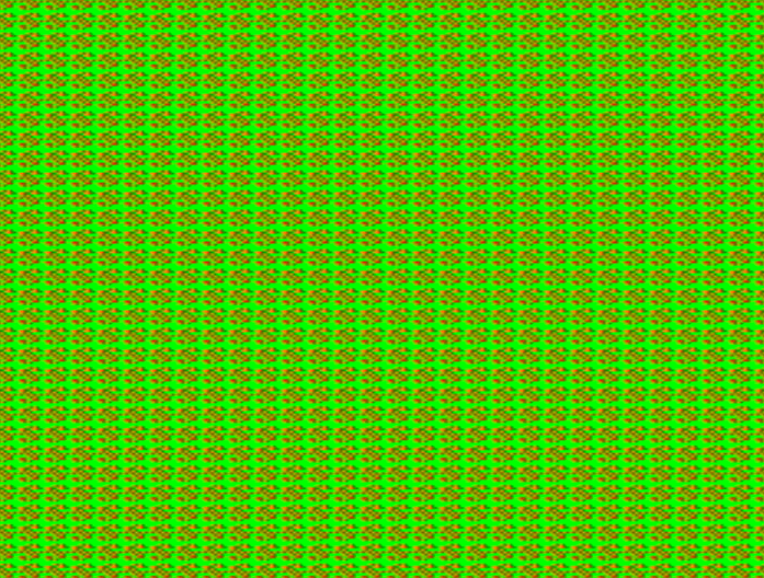
What would be cool would be to be able to load a bitmap image somehow. I’m scared to work with a two dimensional array because it seems not supported in all versions of verilog. I’m trying to scale a smaller bitmap up by dividing the hc and vc counters.
reg pixel = 1'b0; reg [7:0] heart = { {1111111111111111}, {1111111111111111}, {1111111111111111}, {1111101110111111}, {1111000100011111}, {1110111011101111}, {1110111111101111}, {1110111111101111}, {1110111111101111}, {1111011111011111}, {1111101110111111}, {1111110001111111}, {1111111011111111}, {1111111111111111}, {1111111111111111}, {1111111111111111} };... pixel<=heart[(hc>>6)*(vc>>6)]; ... // display green if (hc >= hbp && hc < hfp && pixel == 1'b1)

Almost ! I don’t think the bit shifting or bit selecting – like this [(hc[9:6])*(vc[9:6])]; -is working. I’m trying to divide hc and vc into 16 segments but not finding the right way. Verilog may not support modulo with non powers of 2.
I’ve tried all kinds of different work arounds without any success. It looks like the screen is divided into a 16×16 grid, but within each box there are stripes instead of solid colors…
I’ve changed the size of the image to 12 by 8 so that binary divisions of the horizontal and vertical counters could be used directly because, as I’ve learned recently, verilog thinks in binary. I’ve messed with the padding at the top and bottom of the 256 bit array. I’ve tried countless different syntax for various options of bit selecting and concatenating.
I suppose I could put a massive 640×480 bitmap so that no scaling is necessary, or possibly copy my smaller bitmap into a larger one in an initial block ? It would be so much easier if the size of the screen were the max value of a power of 2, or if I could use a 2D array, or if I could use modulo to test for decimal divisions ! I could also have some more test patterns to input in so I could see in which way the test image is being displayed incorrectly and diagnose the problem there ?
It seems that working with external SRAM and a stream of data that is unorganized into start and end points is comparably easier as there is no framing taking place.
******
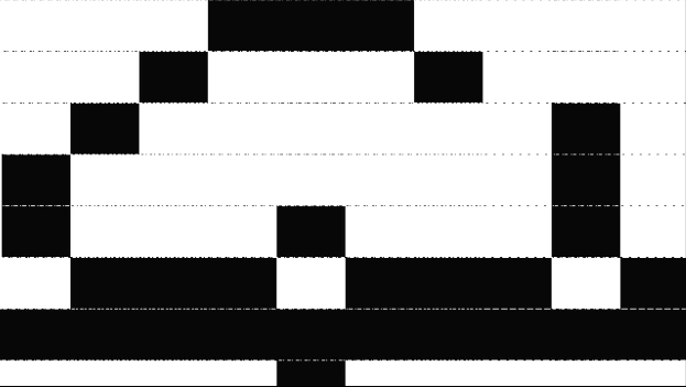
OK, so I misunderstood how a vector works in verilog. It should have the number of elements in the declaration, NOT the bit address depth as I previously had thought. This lack of understanding of how the matrix was represented made everything a total mess.
reg [69:0] heart =

{
10'b1000100011,
10'b0111011101,
10'b0111111101,
10'b0111111011,
10'b1101110111,
10'b1110001111,
10'b1111011111
};
Here’s the code:
`default_nettype none // disable implicit definitions by Verilog
//-----------------------------------------------------------------
// minimalDVID_encoder.vhd : A quick and dirty DVI-D implementation
//
// Author: Mike Field <hamster@snap.net.nz>
//
// DVI-D uses TMDS as the 'on the wire' protocol, where each 8-bit
// value is mapped to one or two 10-bit symbols, depending on how
// many 1s or 0s have been sent. This makes it a DC balanced protocol,
// as a correctly implemented stream will have (almost) an equal
// number of 1s and 0s.
//
// Because of this implementation quite complex. By restricting the
// symbols to a subset of eight symbols, all of which having have
// five ones (and therefore five zeros) this complexity drops away
// leaving a simple implementation. Combined with a DDR register to
// send the symbols the complexity is kept very low.
//-----------------------------------------------------------------

module top(
clk100, hdmi_p, hdmi_n
);

input clk100;
output [3:0] hdmi_p;
output [3:0] hdmi_n;

reg [69:0] heart =

{
10'b1000100011,
10'b0111011101,
10'b0111111101,
10'b0111111011,
10'b1101110111,
10'b1110001111,
10'b1111011111
};


// For holding the outward bound TMDS symbols in the slow and fast domain
reg [9:0] c0_symbol; reg [9:0] c0_high_speed;
reg [9:0] c1_symbol; reg [9:0] c1_high_speed;
reg [9:0] c2_symbol; reg [9:0] c2_high_speed;
reg [9:0] clk_high_speed;

reg [1:0] c2_output_bits;
reg [1:0] c1_output_bits;
reg [1:0] c0_output_bits;
reg [1:0] clk_output_bits;

wire clk_x5;
reg [2:0] latch_high_speed = 3'b100; // Controlling the transfers into the high speed domain

wire vsync, hsync;
wire [1:0] syncs; // To glue the HSYNC and VSYNC into the control character
assign syncs = {vsync, hsync};

// video structure constants
parameter hpixels = 800; // horizontal pixels per line
parameter vlines = 525; // vertical lines per frame
parameter hpulse = 96; // hsync pulse length
parameter vpulse = 2; // vsync pulse length
parameter hbp = 144; // end of horizontal back porch (96 + 48)
parameter hfp = 784; // beginning of horizontal front porch (800 - 16)
parameter vbp = 35; // end of vertical back porch (2 + 33)
parameter vfp = 515; // beginning of vertical front porch (525 - 10)

parameter active_h_pixels = 640;
parameter active_v_pixels = 480;

// registers for storing the horizontal & vertical counters
reg [9:0] vc;
reg [9:0] hc;
// generate sync pulses (active high)
assign vsync = (vc < vpulse);
assign hsync = (hc < hpulse);

reg [7:0] hcount;
reg [7:0] vcount;
reg [7:0] count;
reg pixel;

always @(posedge clk_x5) begin
//-------------------------------------------------------------
// Now take the 10-bit words and take it into the high-speed
// clock domain once every five cycles.
//
// Then send out two bits every clock cycle using DDR output
// registers.
//-------------------------------------------------------------
c0_output_bits <= c0_high_speed[1:0];
c1_output_bits <= c1_high_speed[1:0];
c2_output_bits <= c2_high_speed[1:0];
clk_output_bits <= clk_high_speed[1:0];
if (latch_high_speed[2]) begin // pixel clock 25MHz
c0_high_speed <= c0_symbol;
c1_high_speed <= c1_symbol;
c2_high_speed <= c2_symbol;
clk_high_speed <= 10'b0000011111;
latch_high_speed <= 3'b000;

//multiply the vertical count by 10 to get to the next "row" of the bitmap
count <=(vcount*10)+hcount;
pixel <= heart[count];

//the visible area is 640 pixels horizontally, divide this into 10
if (((hc-hbp)%64==0) && hc >= hbp && hc <= hfp) begin

if(hcount>9) begin
hcount <= 0;
end

else begin
hcount <= hcount+1;
end

end

//the visible area is 480 pixels vertically, divide this into 7.5
if (((vc-vbp)%64==0) && vc >= vbp && vc <= vfp) begin

if(vcount>6) begin
vcount <= 0;
end

else begin
vcount <= vcount+1;
end

end

if (hc < hpixels)
hc <= hc + 1;
else
begin
hc <= 0;
if (vc < vlines)
vc <= vc + 1;
else
vc <= 0;
end
end
else begin
c0_high_speed <= {2'b00, c0_high_speed[9:2]};
c1_high_speed <= {2'b00, c1_high_speed[9:2]};
c2_high_speed <= {2'b00, c2_high_speed[9:2]};
clk_high_speed <= {2'b00, clk_high_speed[9:2]};
latch_high_speed <= latch_high_speed + 1'b1;
end
end

always @(*) // display 100% saturation colourbars
begin
// first check if we're within vertical active video range
if (vc >= vbp && vc < vfp)
begin
// now display different colours every 80 pixels
// while we're within the active horizontal range
// -----------------
// display white bar
if (hc >= hbp && hc < hfp && (pixel == 1'b1))
begin
c2_symbol = 10'b1011110000; // red
c1_symbol = 10'b1011110000; // green
c0_symbol = 10'b1011110000; // blue
end
// display black bar
else if (hc >= hbp && hc < hfp && (pixel == 1'b0))
begin
c2_symbol = 10'b0111110000; // red
c1_symbol = 10'b0111110000; // green
c0_symbol = 10'b0111110000; // blue
end
// we're outside active horizontal range
else
begin
c2_symbol = 10'b1101010100; // red
c1_symbol = 10'b1101010100; // green
//---------------------------------------------
// Channel 0 carries the blue pixels, and also
// includes the HSYNC and VSYNCs during
// the CTL (blanking) periods.
//---------------------------------------------
case (syncs)
2'b00 : c0_symbol = 10'b1101010100;
2'b01 : c0_symbol = 10'b0010101011;
2'b10 : c0_symbol = 10'b0101010100;
default : c0_symbol = 10'b1010101011;
endcase
end
end
// we're outside active vertical range
else
begin
c2_symbol = 10'b1101010100; // red
c1_symbol = 10'b1101010100; // green
//---------------------------------------------
// Channel 0 carries the blue pixels, and also
// includes the HSYNC and VSYNCs during
// the CTL (blanking) periods.
//---------------------------------------------
case (syncs)
2'b00 : c0_symbol = 10'b1101010100;
2'b01 : c0_symbol = 10'b0010101011;
2'b10 : c0_symbol = 10'b0101010100;
default : c0_symbol = 10'b1010101011;
endcase
end
end

// red N
defparam hdmin2.PIN_TYPE = 6'b010000;
defparam hdmin2.IO_STANDARD = "SB_LVCMOS";
SB_IO hdmin2 (
.PACKAGE_PIN (hdmi_n[2]),
.CLOCK_ENABLE (1'b1),
.OUTPUT_CLK (clk_x5),
.OUTPUT_ENABLE (1'b1),
.D_OUT_0 (~c2_output_bits[1]),
.D_OUT_1 (~c2_output_bits[0])
);

// red P
defparam hdmip2.PIN_TYPE = 6'b010000;
defparam hdmip2.IO_STANDARD = "SB_LVCMOS";
SB_IO hdmip2 (
.PACKAGE_PIN (hdmi_p[2]),
.CLOCK_ENABLE (1'b1),
.OUTPUT_CLK (clk_x5),
.OUTPUT_ENABLE (1'b1),
.D_OUT_0 (c2_output_bits[1]),
.D_OUT_1 (c2_output_bits[0])
);

// green N
defparam hdmin1.PIN_TYPE = 6'b010000;
defparam hdmin1.IO_STANDARD = "SB_LVCMOS";
SB_IO hdmin1 (
.PACKAGE_PIN (hdmi_n[1]),
.CLOCK_ENABLE (1'b1),
.OUTPUT_CLK (clk_x5),
.OUTPUT_ENABLE (1'b1),
.D_OUT_0 (~c1_output_bits[1]),
.D_OUT_1 (~c1_output_bits[0])
);

// green P
defparam hdmip1.PIN_TYPE = 6'b010000;
defparam hdmip1.IO_STANDARD = "SB_LVCMOS";
SB_IO hdmip1 (
.PACKAGE_PIN (hdmi_p[1]),
.CLOCK_ENABLE (1'b1),
.OUTPUT_CLK (clk_x5),
.OUTPUT_ENABLE (1'b1),
.D_OUT_0 (c1_output_bits[1]),
.D_OUT_1 (c1_output_bits[0])
);


// blue N
defparam hdmin0.PIN_TYPE = 6'b010000;
defparam hdmin0.IO_STANDARD = "SB_LVCMOS";
SB_IO hdmin0 (
.PACKAGE_PIN (hdmi_n[0]),
.CLOCK_ENABLE (1'b1),
.OUTPUT_CLK (clk_x5),
.OUTPUT_ENABLE (1'b1),
.D_OUT_0 (~c0_output_bits[1]),
.D_OUT_1 (~c0_output_bits[0])
);

// blue P
defparam hdmip0.PIN_TYPE = 6'b010000;
defparam hdmip0.IO_STANDARD = "SB_LVCMOS";
SB_IO hdmip0 (
.PACKAGE_PIN (hdmi_p[0]),
.CLOCK_ENABLE (1'b1),
.OUTPUT_CLK (clk_x5),
.OUTPUT_ENABLE (1'b1),
.D_OUT_0 (c0_output_bits[1]),
.D_OUT_1 (c0_output_bits[0])
);

// clock N
defparam hdmin3.PIN_TYPE = 6'b010000;
defparam hdmin3.IO_STANDARD = "SB_LVCMOS";
SB_IO hdmin3 (
.PACKAGE_PIN (hdmi_n[3]),
.CLOCK_ENABLE (1'b1),
.OUTPUT_CLK (clk_x5),
.OUTPUT_ENABLE (1'b1),
.D_OUT_0 (~clk_output_bits[1]),
.D_OUT_1 (~clk_output_bits[0])
);


// clock P
defparam hdmip3.PIN_TYPE = 6'b010000;
defparam hdmip3.IO_STANDARD = "SB_LVCMOS";
SB_IO hdmip3 (
.PACKAGE_PIN (hdmi_p[3]),
.CLOCK_ENABLE (1'b1),
.OUTPUT_CLK (clk_x5),
.OUTPUT_ENABLE (1'b1),
.D_OUT_0 (clk_output_bits[1]),
.D_OUT_1 (clk_output_bits[0])
);
// D_OUT_0 and D_OUT_1 swapped?
// https://github.com/YosysHQ/yosys/issues/330


SB_PLL40_PAD #(
.FEEDBACK_PATH ("SIMPLE"),
.DIVR (4'b0000),
.DIVF (7'b0001001),
.DIVQ (3'b011),
.FILTER_RANGE (3'b101)
) uut (
.RESETB (1'b1),
.BYPASS (1'b0),
.PACKAGEPIN (clk100),
.PLLOUTGLOBAL (clk_x5) // DVI clock 125MHz
);

endmodule
I have a tool that converts images into 0s and 1s of any square size :
https://www.dcode.fr/binary-image
I am trying to get to the bottom of how to expand the register size to show larger images. Everytime I try I either get bits that don’t correspond to the initialized values, or I get an out of sync image.
I tried to diagram the states of various counters here ![]()
In parallel, I’m reading that initializing values in a register in IceCube 2 is problematic. Some posts say that IceCube can only initialize memory as 0. Others say you should use an initial block, or a reset signal which changes the values of the memory.
After reading the IceCube2 user’s guide, I found out you can inspect the BRAM created in your design in the floor planner :
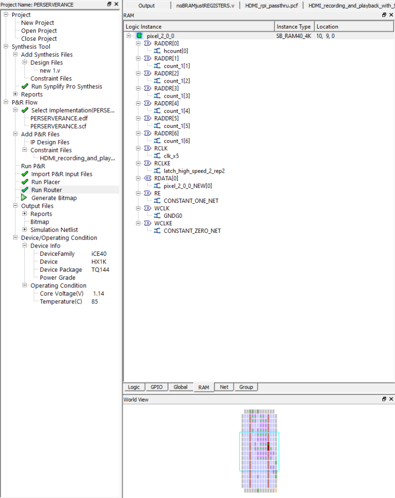
You must use non-blocking (<=) assignments to get data in and out of RAM :
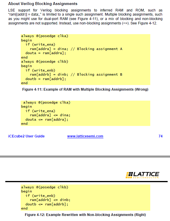
You can instantiate a ROM like this with case of if statements :
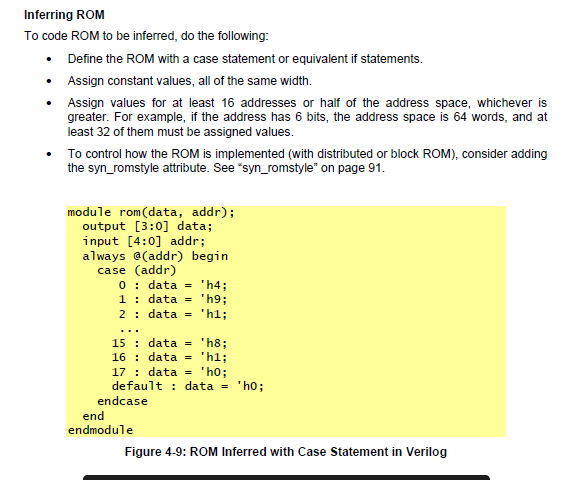
I’m currently trying to use readmemh with a full source path for the file, I don’t think it is working however.
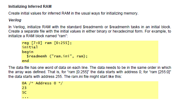
N.B. Good to know that to reverse the order of the data in the RAM you can change from 255:0 to 0:255.
This appears to be working with the following code :
reg [7:0] ram [0:255];

initial
begin
$readmemh ("../../../../../Users/jm225306/OneDrive - De Vinci/Bureau/JONAH PERSO/# ICE 40 HX8K FPGA BOARD/CYBER CAMPUS DESIGN/4_SRAM+HDMI/ram.ini", ram);
end

....

with the ram.ini file looking like this :

0A
23
5C
0A
23
5C
0A
23
5C
0A
23
5C
0A
23
5C
0A
23
5C
0A
23
5C
0A
23
5C
0A
23
5C
0A
23
5C
0A
23
5C
0A
23
5C
0A
23
5C
0A
23
5C
0A
23
5C
0A
23
5C
0A
23
5C
0A
23
5C
0A
23
5C
0A
23
5C
0A
23
5C
0A
23
5C
0A
23
5C
0A
23
5C
0A
23
5C
0A
23
5C
0A
23
5C
0A
23
5C
0A
23
5C
0A
23
5C
******
Cool project doing face detection in real time with an FPGA using spatial and temporal filters :
http://people.ece.cornell.edu/land/courses/eceprojectsland/STUDENTPROJ/2012to2013/tnn7/tnn7_report_201212141110.pdf
An example of a heat camera developed in part using an FPGA :
https://www.researchgate.net/publication/319118786_A_low_cost_FPGA_based_thermal_imaging_camera_for_fault_detection_in_PV_panels
*******
Reasons to work with hardware vs. software synths :
- charisma of the physical instrument object, muscle memory of the instrument, and the fun of it !
- limits good for creativity
- no pc needed
- you can make your own custom input (ADC) and output (amp) stages
- performance and low start-up time
************
I have a simple code to display a 64 bit bitmap :

`default_nettype none // disable implicit definitions by Verilog
//-----------------------------------------------------------------
// minimalDVID_encoder.vhd : A quick and dirty DVI-D implementation
//
// Author: Mike Field <hamster@snap.net.nz>
//
// DVI-D uses TMDS as the 'on the wire' protocol, where each 8-bit
// value is mapped to one or two 10-bit symbols, depending on how
// many 1s or 0s have been sent. This makes it a DC balanced protocol,
// as a correctly implemented stream will have (almost) an equal
// number of 1s and 0s.
//
// Because of this implementation quite complex. By restricting the
// symbols to a subset of eight symbols, all of which having have
// five ones (and therefore five zeros) this complexity drops away
// leaving a simple implementation. Combined with a DDR register to
// send the symbols the complexity is kept very low.
//-----------------------------------------------------------------

module top(
clk100, hdmi_p, hdmi_n
);

input clk100;
output [3:0] hdmi_p;
output [3:0] hdmi_n;


reg [0:63] heart =

{
8'b11111111,
8'b00010001,
8'b01101101,
8'b01111101,
8'b01111101,
8'b10111011,
8'b11000111,
8'b11101111
};

reg [10:0] hcount;
reg [10:0] vcount;
reg pixel;


// For holding the outward bound TMDS symbols in the slow and fast domain
reg [9:0] c0_symbol; reg [9:0] c0_high_speed;
reg [9:0] c1_symbol; reg [9:0] c1_high_speed;
reg [9:0] c2_symbol; reg [9:0] c2_high_speed;
reg [9:0] clk_high_speed;

reg [1:0] c2_output_bits;
reg [1:0] c1_output_bits;
reg [1:0] c0_output_bits;
reg [1:0] clk_output_bits;

wire clk_x5;
reg [2:0] latch_high_speed = 3'b100; // Controlling the transfers into the high speed domain

wire vsync, hsync;
wire [1:0] syncs; // To glue the HSYNC and VSYNC into the control character
assign syncs = {vsync, hsync};

// video structure constants
parameter hpixels = 800; // horizontal pixels per line
parameter vlines = 525; // vertical lines per frame
parameter hpulse = 96; // hsync pulse length
parameter vpulse = 2; // vsync pulse length
parameter hbp = 144; // end of horizontal back porch (96 + 48)
parameter hfp = 784; // beginning of horizontal front porch (800 - 16)
parameter vbp = 35; // end of vertical back porch (2 + 33)
parameter vfp = 515; // beginning of vertical front porch (525 - 10)

// registers for storing the horizontal & vertical counters
reg [9:0] vc;
reg [9:0] hc;
// generate sync pulses (active high)
assign vsync = (vc < vpulse);
assign hsync = (hc < hpulse);

always @(posedge clk_x5) begin
//-------------------------------------------------------------
// Now take the 10-bit words and take it into the high-speed
// clock domain once every five cycles.
//
// Then send out two bits every clock cycle using DDR output
// registers.
//-------------------------------------------------------------
c0_output_bits <= c0_high_speed[1:0];
c1_output_bits <= c1_high_speed[1:0];
c2_output_bits <= c2_high_speed[1:0];
clk_output_bits <= clk_high_speed[1:0];
if (latch_high_speed[2]) begin // pixel clock 25MHz
c0_high_speed <= c0_symbol;
c1_high_speed <= c1_symbol;
c2_high_speed <= c2_symbol;
clk_high_speed <= 10'b0000011111;
latch_high_speed <= 3'b000;
if (hc < hpixels)
hc <= hc + 1;
else
begin
hc <= 0;
if (vc < vlines)
vc <= vc + 1;
else
vc <= 0;
end
end
else begin
c0_high_speed <= {2'b00, c0_high_speed[9:2]};
c1_high_speed <= {2'b00, c1_high_speed[9:2]};
c2_high_speed <= {2'b00, c2_high_speed[9:2]};
clk_high_speed <= {2'b00, clk_high_speed[9:2]};
latch_high_speed <= latch_high_speed + 1'b1;
end
end

always @(*) // display 100% saturation colourbars
begin
pixel = heart[hcount+vcount];
// first check if we're within vertical active video range
if (vc >= vbp && vc < vfp)
begin
// now display different colours every 80 pixels
// while we're within the active horizontal range
// -----------------

if (vc >= vbp && vc < (vbp+60))
begin
vcount = 0;
end

else if (vc >= (vbp+60) && vc < (vbp+120))
begin
vcount = 8;
end

else if (vc >= (vbp+120) && vc < (vbp+180))
begin
vcount = 16;
end

else if (vc >= (vbp+180) && vc < (vbp+240))
begin
vcount = 24;
end

else if (vc >= (vbp+240) && vc < (vbp+300))
begin
vcount = 32;
end

else if (vc >= (vbp+300) && vc < (vbp+360))
begin
vcount = 40;
end

else if (vc >= (vbp+360) && vc < (vbp+420))
begin
vcount = 48;
end

else
begin
vcount = 56;
end


// display white bar
if (hc >= hbp && hc < hfp)
begin
if (pixel == 1'b1) begin
//yellow
c2_symbol = 10'b1011110000; // red
c1_symbol = 10'b1011110000; // green
c0_symbol = 10'b0111110000; // blue
end
else begin
//magenta
c2_symbol = 10'b1011110000; // red
c1_symbol = 10'b0111110000; // green
c0_symbol = 10'b1011110000; // blue
end


if (hc >= hbp && hc < (hbp+80))
begin
hcount = 0;
end

else if (hc >= (hbp+80) && hc < (hbp+160))
begin
hcount = 1;
end

else if (hc >= (hbp+160) && hc < (hbp+240))
begin
hcount = 2;
end

else if (hc >= (hbp+240) && hc < (hbp+320))
begin
hcount = 3;
end

else if (hc >= (hbp+320) && hc < (hbp+400))
begin
hcount = 4;
end

else if (hc >= (hbp+400) && hc < (hbp+480))
begin
hcount = 5;
end

else if (hc >= (hbp+480) && hc < (hbp+560))
begin
hcount = 6;
end

else if (hc >= (hbp+560) && hc < hfp)
begin
hcount = 7;
end


end


// we're outside active horizontal range
else
begin
c2_symbol = 10'b1101010100; // red
c1_symbol = 10'b1101010100; // green
//---------------------------------------------
// Channel 0 carries the blue pixels, and also
// includes the HSYNC and VSYNCs during
// the CTL (blanking) periods.
//---------------------------------------------
case (syncs)
2'b00 : c0_symbol = 10'b1101010100;
2'b01 : c0_symbol = 10'b0010101011;
2'b10 : c0_symbol = 10'b0101010100;
default : c0_symbol = 10'b1010101011;
endcase
end
end
// we're outside active vertical range
else
begin
c2_symbol = 10'b1101010100; // red
c1_symbol = 10'b1101010100; // green
//---------------------------------------------
// Channel 0 carries the blue pixels, and also
// includes the HSYNC and VSYNCs during
// the CTL (blanking) periods.
//---------------------------------------------
case (syncs)
2'b00 : c0_symbol = 10'b1101010100;
2'b01 : c0_symbol = 10'b0010101011;
2'b10 : c0_symbol = 10'b0101010100;
default : c0_symbol = 10'b1010101011;
endcase
end
end

// red N
defparam hdmin2.PIN_TYPE = 6'b010000;
defparam hdmin2.IO_STANDARD = "SB_LVCMOS";
SB_IO hdmin2 (
.PACKAGE_PIN (hdmi_n[2]),
.CLOCK_ENABLE (1'b1),
.OUTPUT_CLK (clk_x5),
.OUTPUT_ENABLE (1'b1),
.D_OUT_0 (~c2_output_bits[1]),
.D_OUT_1 (~c2_output_bits[0])
);

// red P
defparam hdmip2.PIN_TYPE = 6'b010000;
defparam hdmip2.IO_STANDARD = "SB_LVCMOS";
SB_IO hdmip2 (
.PACKAGE_PIN (hdmi_p[2]),
.CLOCK_ENABLE (1'b1),
.OUTPUT_CLK (clk_x5),
.OUTPUT_ENABLE (1'b1),
.D_OUT_0 (c2_output_bits[1]),
.D_OUT_1 (c2_output_bits[0])
);

// green N
defparam hdmin1.PIN_TYPE = 6'b010000;
defparam hdmin1.IO_STANDARD = "SB_LVCMOS";
SB_IO hdmin1 (
.PACKAGE_PIN (hdmi_n[1]),
.CLOCK_ENABLE (1'b1),
.OUTPUT_CLK (clk_x5),
.OUTPUT_ENABLE (1'b1),
.D_OUT_0 (~c1_output_bits[1]),
.D_OUT_1 (~c1_output_bits[0])
);

// green P
defparam hdmip1.PIN_TYPE = 6'b010000;
defparam hdmip1.IO_STANDARD = "SB_LVCMOS";
SB_IO hdmip1 (
.PACKAGE_PIN (hdmi_p[1]),
.CLOCK_ENABLE (1'b1),
.OUTPUT_CLK (clk_x5),
.OUTPUT_ENABLE (1'b1),
.D_OUT_0 (c1_output_bits[1]),
.D_OUT_1 (c1_output_bits[0])
);


// blue N
defparam hdmin0.PIN_TYPE = 6'b010000;
defparam hdmin0.IO_STANDARD = "SB_LVCMOS";
SB_IO hdmin0 (
.PACKAGE_PIN (hdmi_n[0]),
.CLOCK_ENABLE (1'b1),
.OUTPUT_CLK (clk_x5),
.OUTPUT_ENABLE (1'b1),
.D_OUT_0 (~c0_output_bits[1]),
.D_OUT_1 (~c0_output_bits[0])
);

// blue P
defparam hdmip0.PIN_TYPE = 6'b010000;
defparam hdmip0.IO_STANDARD = "SB_LVCMOS";
SB_IO hdmip0 (
.PACKAGE_PIN (hdmi_p[0]),
.CLOCK_ENABLE (1'b1),
.OUTPUT_CLK (clk_x5),
.OUTPUT_ENABLE (1'b1),
.D_OUT_0 (c0_output_bits[1]),
.D_OUT_1 (c0_output_bits[0])
);

// clock N
defparam hdmin3.PIN_TYPE = 6'b010000;
defparam hdmin3.IO_STANDARD = "SB_LVCMOS";
SB_IO hdmin3 (
.PACKAGE_PIN (hdmi_n[3]),
.CLOCK_ENABLE (1'b1),
.OUTPUT_CLK (clk_x5),
.OUTPUT_ENABLE (1'b1),
.D_OUT_0 (~clk_output_bits[1]),
.D_OUT_1 (~clk_output_bits[0])
);


// clock P
defparam hdmip3.PIN_TYPE = 6'b010000;
defparam hdmip3.IO_STANDARD = "SB_LVCMOS";
SB_IO hdmip3 (
.PACKAGE_PIN (hdmi_p[3]),
.CLOCK_ENABLE (1'b1),
.OUTPUT_CLK (clk_x5),
.OUTPUT_ENABLE (1'b1),
.D_OUT_0 (clk_output_bits[1]),
.D_OUT_1 (clk_output_bits[0])
);
// D_OUT_0 and D_OUT_1 swapped?
// https://github.com/YosysHQ/yosys/issues/330


SB_PLL40_PAD #(
.FEEDBACK_PATH ("SIMPLE"),
.DIVR (4'b0000),
.DIVF (7'b0001001),
.DIVQ (3'b011),
.FILTER_RANGE (3'b101)
) uut (
.RESETB (1'b1),
.BYPASS (1'b0),
.PACKAGEPIN (clk100),
.PLLOUTGLOBAL (clk_x5) // DVI clock 125MHz
);

endmodule
******
Now I am trying to use hc and vc directly as the index of a 640×480 array. I used this site (https://www.dcode.fr/binary-image) to convert an image that was 640×480. I then used Notepad++ to add ‘640’b’ at the start of each line and ‘,’ at the end of each line. To do this, in the Find and Replace dialog box select Regular expression and use ‘^’ for the start of the sentence and ‘$’ for the end of the sentence.
The Ice40HX1K has 64 kbit of memory, 16 x 4kbit chunks. I am asking it to remember more than 300K bits.
//don't forget to subtract 1 from the total 640x480 (307200)

reg [0:307199] heart =

{
640'b .... ,
};

reg pixel;

...

always @(*)
begin
pixel = heart[hc+(vc*640)];

if (vc >= vbp && vc < vfp)
begin
// now display different colours every 80 pixels
// while we're within the active horizontal range
// -----------------

// display white bar
if (hc >= hbp && hc < hfp)
begin
if (pixel == 1'b1) begin
//yellow
c2_symbol = 10'b1011110000; // red
c1_symbol = 10'b1011110000; // green
c0_symbol = 10'b0111110000; // blue
end
else begin
//magenta
c2_symbol = 10'b1011110000; // red
c1_symbol = 10'b0111110000; // green
c0_symbol = 10'b1011110000; // blue
end


end


// we're outside the h range...

...
************
I have 16 bit by 16 !

`default_nettype none // disable implicit definitions by Verilog
//-----------------------------------------------------------------
// minimalDVID_encoder.vhd : A quick and dirty DVI-D implementation
//
// Author: Mike Field <hamster@snap.net.nz>
//
// DVI-D uses TMDS as the 'on the wire' protocol, where each 8-bit
// value is mapped to one or two 10-bit symbols, depending on how
// many 1s or 0s have been sent. This makes it a DC balanced protocol,
// as a correctly implemented stream will have (almost) an equal
// number of 1s and 0s.
//
// Because of this implementation quite complex. By restricting the
// symbols to a subset of eight symbols, all of which having have
// five ones (and therefore five zeros) this complexity drops away
// leaving a simple implementation. Combined with a DDR register to
// send the symbols the complexity is kept very low.
//-----------------------------------------------------------------

module top(
clk100, hdmi_p, hdmi_n
);

input clk100;
output [3:0] hdmi_p;
output [3:0] hdmi_n;


reg [0:255] heart =

{
16'b1111111111111111,
16'b0001000100010001,
16'b0110110101101101,
16'b0111110101111101,
16'b0111110101111101,
16'b1011101110111011,
16'b1100011111000111,
16'b1110111111101111,
16'b1111111111111111,
16'b0001000100010001,
16'b0110110101101101,
16'b0111110101111101,
16'b0111110101111101,
16'b1011101110111011,
16'b1100011111000111,
16'b1110111111101111
};

reg [10:0] hcount;
reg [10:0] vcount;
reg pixel;


// For holding the outward bound TMDS symbols in the slow and fast domain
reg [9:0] c0_symbol; reg [9:0] c0_high_speed;
reg [9:0] c1_symbol; reg [9:0] c1_high_speed;
reg [9:0] c2_symbol; reg [9:0] c2_high_speed;
reg [9:0] clk_high_speed;

reg [1:0] c2_output_bits;
reg [1:0] c1_output_bits;
reg [1:0] c0_output_bits;
reg [1:0] clk_output_bits;

wire clk_x5;
reg [2:0] latch_high_speed = 3'b100; // Controlling the transfers into the high speed domain

wire vsync, hsync;
wire [1:0] syncs; // To glue the HSYNC and VSYNC into the control character
assign syncs = {vsync, hsync};

// video structure constants
parameter hpixels = 800; // horizontal pixels per line
parameter vlines = 525; // vertical lines per frame
parameter hpulse = 96; // hsync pulse length
parameter vpulse = 2; // vsync pulse length
parameter hbp = 144; // end of horizontal back porch (96 + 48)
parameter hfp = 784; // beginning of horizontal front porch (800 - 16)
parameter vbp = 35; // end of vertical back porch (2 + 33)
parameter vfp = 515; // beginning of vertical front porch (525 - 10)

// registers for storing the horizontal & vertical counters
reg [9:0] vc;
reg [9:0] hc;
// generate sync pulses (active high)
assign vsync = (vc < vpulse);
assign hsync = (hc < hpulse);

always @(posedge clk_x5) begin
//-------------------------------------------------------------
// Now take the 10-bit words and take it into the high-speed
// clock domain once every five cycles.
//
// Then send out two bits every clock cycle using DDR output
// registers.
//-------------------------------------------------------------
c0_output_bits <= c0_high_speed[1:0];
c1_output_bits <= c1_high_speed[1:0];
c2_output_bits <= c2_high_speed[1:0];
clk_output_bits <= clk_high_speed[1:0];
if (latch_high_speed[2]) begin // pixel clock 25MHz
c0_high_speed <= c0_symbol;
c1_high_speed <= c1_symbol;
c2_high_speed <= c2_symbol;
clk_high_speed <= 10'b0000011111;
latch_high_speed <= 3'b000;
if (hc < hpixels)
hc <= hc + 1;
else
begin
hc <= 0;
if (vc < vlines)
vc <= vc + 1;
else
vc <= 0;
end
end
else begin
c0_high_speed <= {2'b00, c0_high_speed[9:2]};
c1_high_speed <= {2'b00, c1_high_speed[9:2]};
c2_high_speed <= {2'b00, c2_high_speed[9:2]};
clk_high_speed <= {2'b00, clk_high_speed[9:2]};
latch_high_speed <= latch_high_speed + 1'b1;
end
end

always @(*) // display 100% saturation colourbars
begin
pixel = heart[hcount+vcount];
// first check if we're within vertical active video range
if (vc >= vbp && vc < vfp)
begin
// now display different colours every 80 pixels
// while we're within the active horizontal range
// -----------------
if (vc >= vbp && vc < (vbp+30)) vcount = 0;
else if (vc >= (vbp+30) && vc < (vbp+60)) vcount = 16;
else if (vc >= (vbp+60) && vc < (vbp+90)) vcount = 32;
else if (vc >= (vbp+90) && vc < (vbp+120)) vcount = 48;
else if (vc >= (vbp+120) && vc < (vbp+150)) vcount = 64;
else if (vc >= (vbp+150) && vc < (vbp+180)) vcount = 80;
else if (vc >= (vbp+180) && vc < (vbp+210)) vcount = 96;
else if (vc >= (vbp+210) && vc < (vbp+240)) vcount = 112;
else if (vc >= (vbp+240) && vc < (vbp+270)) vcount = 128;
else if (vc >= (vbp+270) && vc < (vbp+300)) vcount = 144;
else if (vc >= (vbp+300) && vc < (vbp+330)) vcount = 160;
else if (vc >= (vbp+330) && vc < (vbp+360)) vcount = 176;
else if (vc >= (vbp+360) && vc < (vbp+390)) vcount = 192;
else if (vc >= (vbp+390) && vc < (vbp+420)) vcount = 208;
else if (vc >= (vbp+420) && vc < (vbp+450)) vcount = 224;
else vcount = 240;

// display white bar
if (hc >= hbp && hc < hfp)
begin
if (pixel == 1'b1) begin
//yellow
c2_symbol = 10'b1011110000; // red
c1_symbol = 10'b1011110000; // green
c0_symbol = 10'b0111110000; // blue
end
else begin
//magenta
c2_symbol = 10'b1011110000; // red
c1_symbol = 10'b0111110000; // green
c0_symbol = 10'b1011110000; // blue
end


if (hc >= hbp && hc < (hbp+40)) hcount = 0;
else if (hc >= (hbp+40) && hc < (hbp+80)) hcount = 1;
else if (hc >= (hbp+80) && hc < (hbp+120)) hcount = 2;
else if (hc >= (hbp+120) && hc < (hbp+160)) hcount = 3;
else if (hc >= (hbp+160) && hc < (hbp+200)) hcount = 4;
else if (hc >= (hbp+200) && hc < (hbp+240)) hcount = 5;
else if (hc >= (hbp+240) && hc < (hbp+280)) hcount = 6;
else if (hc >= (hbp+280) && hc < (hbp+320)) hcount = 7;
else if (hc >= (hbp+320) && hc < (hbp+380)) hcount = 8;
else if (hc >= (hbp+380) && hc < (hbp+420)) hcount = 9;
else if (hc >= (hbp+420) && hc < (hbp+440)) hcount = 10;
else if (hc >= (hbp+440) && hc < (hbp+480)) hcount = 11;
else if (hc >= (hbp+480) && hc < (hbp+520)) hcount = 12;
else if (hc >= (hbp+520) && hc < (hbp+560)) hcount = 13;
else if (hc >= (hbp+560) && hc < (hbp+600)) hcount = 14;
else hcount = 15;


end


// we're outside active horizontal range
else
begin
c2_symbol = 10'b1101010100; // red
c1_symbol = 10'b1101010100; // green
//---------------------------------------------
// Channel 0 carries the blue pixels, and also
// includes the HSYNC and VSYNCs during
// the CTL (blanking) periods.
//---------------------------------------------
case (syncs)
2'b00 : c0_symbol = 10'b1101010100;
2'b01 : c0_symbol = 10'b0010101011;
2'b10 : c0_symbol = 10'b0101010100;
default : c0_symbol = 10'b1010101011;
endcase
end
end
// we're outside active vertical range
else
begin
c2_symbol = 10'b1101010100; // red
c1_symbol = 10'b1101010100; // green
//---------------------------------------------
// Channel 0 carries the blue pixels, and also
// includes the HSYNC and VSYNCs during
// the CTL (blanking) periods.
//---------------------------------------------
case (syncs)
2'b00 : c0_symbol = 10'b1101010100;
2'b01 : c0_symbol = 10'b0010101011;
2'b10 : c0_symbol = 10'b0101010100;
default : c0_symbol = 10'b1010101011;
endcase
end
end

// red N
defparam hdmin2.PIN_TYPE = 6'b010000;
defparam hdmin2.IO_STANDARD = "SB_LVCMOS";
SB_IO hdmin2 (
.PACKAGE_PIN (hdmi_n[2]),
.CLOCK_ENABLE (1'b1),
.OUTPUT_CLK (clk_x5),
.OUTPUT_ENABLE (1'b1),
.D_OUT_0 (~c2_output_bits[1]),
.D_OUT_1 (~c2_output_bits[0])
);

// red P
defparam hdmip2.PIN_TYPE = 6'b010000;
defparam hdmip2.IO_STANDARD = "SB_LVCMOS";
SB_IO hdmip2 (
.PACKAGE_PIN (hdmi_p[2]),
.CLOCK_ENABLE (1'b1),
.OUTPUT_CLK (clk_x5),
.OUTPUT_ENABLE (1'b1),
.D_OUT_0 (c2_output_bits[1]),
.D_OUT_1 (c2_output_bits[0])
);

// green N
defparam hdmin1.PIN_TYPE = 6'b010000;
defparam hdmin1.IO_STANDARD = "SB_LVCMOS";
SB_IO hdmin1 (
.PACKAGE_PIN (hdmi_n[1]),
.CLOCK_ENABLE (1'b1),
.OUTPUT_CLK (clk_x5),
.OUTPUT_ENABLE (1'b1),
.D_OUT_0 (~c1_output_bits[1]),
.D_OUT_1 (~c1_output_bits[0])
);

// green P
defparam hdmip1.PIN_TYPE = 6'b010000;
defparam hdmip1.IO_STANDARD = "SB_LVCMOS";
SB_IO hdmip1 (
.PACKAGE_PIN (hdmi_p[1]),
.CLOCK_ENABLE (1'b1),
.OUTPUT_CLK (clk_x5),
.OUTPUT_ENABLE (1'b1),
.D_OUT_0 (c1_output_bits[1]),
.D_OUT_1 (c1_output_bits[0])
);


// blue N
defparam hdmin0.PIN_TYPE = 6'b010000;
defparam hdmin0.IO_STANDARD = "SB_LVCMOS";
SB_IO hdmin0 (
.PACKAGE_PIN (hdmi_n[0]),
.CLOCK_ENABLE (1'b1),
.OUTPUT_CLK (clk_x5),
.OUTPUT_ENABLE (1'b1),
.D_OUT_0 (~c0_output_bits[1]),
.D_OUT_1 (~c0_output_bits[0])
);

// blue P
defparam hdmip0.PIN_TYPE = 6'b010000;
defparam hdmip0.IO_STANDARD = "SB_LVCMOS";
SB_IO hdmip0 (
.PACKAGE_PIN (hdmi_p[0]),
.CLOCK_ENABLE (1'b1),
.OUTPUT_CLK (clk_x5),
.OUTPUT_ENABLE (1'b1),
.D_OUT_0 (c0_output_bits[1]),
.D_OUT_1 (c0_output_bits[0])
);

// clock N
defparam hdmin3.PIN_TYPE = 6'b010000;
defparam hdmin3.IO_STANDARD = "SB_LVCMOS";
SB_IO hdmin3 (
.PACKAGE_PIN (hdmi_n[3]),
.CLOCK_ENABLE (1'b1),
.OUTPUT_CLK (clk_x5),
.OUTPUT_ENABLE (1'b1),
.D_OUT_0 (~clk_output_bits[1]),
.D_OUT_1 (~clk_output_bits[0])
);


// clock P
defparam hdmip3.PIN_TYPE = 6'b010000;
defparam hdmip3.IO_STANDARD = "SB_LVCMOS";
SB_IO hdmip3 (
.PACKAGE_PIN (hdmi_p[3]),
.CLOCK_ENABLE (1'b1),
.OUTPUT_CLK (clk_x5),
.OUTPUT_ENABLE (1'b1),
.D_OUT_0 (clk_output_bits[1]),
.D_OUT_1 (clk_output_bits[0])
);
// D_OUT_0 and D_OUT_1 swapped?
// https://github.com/YosysHQ/yosys/issues/330


SB_PLL40_PAD #(
.FEEDBACK_PATH ("SIMPLE"),
.DIVR (4'b0000),
.DIVF (7'b0001001),
.DIVQ (3'b011),
.FILTER_RANGE (3'b101)
) uut (
.RESETB (1'b1),
.BYPASS (1'b0),
.PACKAGEPIN (clk100),
.PLLOUTGLOBAL (clk_x5) // DVI clock 125MHz
);

endmodule


******
Finally, I have a non painful way of displaying images. This is the heart of it :
//divide hc (once in visible area) by 4, divide vc (once in visible area) by 4 and then multiply it by the row width

pixel = heart[(((hc-hbp)>>2)+(((vc-vbp)>>2)*160))];
IceCube2 appears to be happy with register sizes that are not powers of two and that extend beyond 4K. That said there were no BRAMs inferred in this and I’m around 900/1.2K (!!) blocks used up. Next step is to figure out how to use BRAM and the same simple binary division principle.
`default_nettype none // disable implicit definitions by Verilog
//-----------------------------------------------------------------
// minimalDVID_encoder.vhd : A quick and dirty DVI-D implementation
//
// Author: Mike Field <hamster@snap.net.nz>
//
// DVI-D uses TMDS as the 'on the wire' protocol, where each 8-bit
// value is mapped to one or two 10-bit symbols, depending on how
// many 1s or 0s have been sent. This makes it a DC balanced protocol,
// as a correctly implemented stream will have (almost) an equal
// number of 1s and 0s.
//
// Because of this implementation quite complex. By restricting the
// symbols to a subset of eight symbols, all of which having have
// five ones (and therefore five zeros) this complexity drops away
// leaving a simple implementation. Combined with a DDR register to
// send the symbols the complexity is kept very low.
//-----------------------------------------------------------------

module top(
clk100, hdmi_p, hdmi_n
);

input clk100;
output [3:0] hdmi_p;
output [3:0] hdmi_n;

//160x120
reg [0:19199] heart =

{
160'b0000000000000000000000000000000000000011111111111111111111111111111111111101111100001111110000011111111111111111111111111111111111111111111111111111111111111111,
160'b0000000000000000000000000000000000000011111111111111111111111111111111111100000111111111111111000011100111111111111111111111111111111111111111111111111111111111,
160'b0000000000000000000000000000000000000011111111111111111111111111111111111111111111111111111111111111101111111111111111111111111111111111111111111111111111111111,
160'b0000000000000000000000000000000000110000110001111111111111111111111111111111111111111111111111111111111111111111111111111111111111111111111111111111111111111111,
160'b0000000000000000000000000000000000110000011011111111111111111111111111111111111111111111111111111111111111110111111111111111111111111111111111111111111111111111,
160'b0000000000000000000000000000000000110000011111111111111111111111111111111111111111111111111111111111111111100111111111111111111111111111111111111111111111111111,
160'b0000000000000000000000000000000000000000011111111111111111111111111111111111111111111111111111111111111111111111000111111111111111111111111111111111111111111111,
160'b0000000000000000000000000000000000000000011111111111111111111111111111111111111111111111111111111111111111111111000111111111111111111111111111111111111111111111,
160'b0000000000000000000000000000000000000000001111111111111111111111111111111111111111111111111111111111111111111111111111111111111111111111111111111111111111111111,
160'b0000000000000000000000000000000000000000001101111111111111111111111111111111111111111111111111111111111111111111111101111111111111111111111111111111111111111111,
160'b0000000000000000000000000000000000000000101111111111111111111111111111111111111111111111111111111111111111111111111111111111111111111111111111111111111111111111,
160'b0000000000000000000000000000000000000000111111111111111111111111111111111111111111111111111111111111111111111111111111111111111111111111111111111111111111111111,
160'b0000000000000000000000000000000000000000111111111111111111111111001111111111111111111111111111111111111111111111111111111111111111111111111111111111111111111111,
160'b0000000000000000000000000000000000000001111001111111111111111111111111111111111111111111111111111111111111111111111111101111111111111111111111111111111111111111,
160'b0000000000000000000000000000000111000001111001111111111111111111111111111111111111111111111111111111111111111111111111111111111111111111111111111111111111111111,
160'b0000000000000000000000000000000010011001111011111111111111111111111111111111111111111111111111111111111111111111111111111111111111111111111111111111111111111111,
160'b0000000000000000000000000000000000000111111111111111111111111111111111111111111111111111111111111111111111111111111111111111111111111111111111111111111111111111,
160'b0000000000000000000000000000000000001111111111111111111111111111111111111111111111111111111111111111111111111111111111111111111111111111111111111111111111111111,
160'b0000000000000000000000000000000000001111111111111111111111111111111111111111111111111111111111111111111111111111111111111111111111111111111111111111111111111111,
160'b0000000000000000000000000000000000001111111111111111111111111111111111111111111111111111111111111111111111111111111111111111111111111111111111111111111111111111,
160'b0000000000000000000000000000000000011111111111111111111111111111111111111111111111111111111111111111111111111111111111111111111111111111111111111111111111111111,
160'b0000000000000000000000000000000000111111111111111111111111111111111111111111111111111111111111111111111111111111111111111111111111111111111111111111111111111111,
160'b0000000000000000000000000000000001111111111111111111111111111111111111111111111111111111111111111111111111111111111111111111111111111111111111111111111111111111,
160'b0000000000000000000000000000000000111111111111111111111111111111111111111111111111111111111111111111111111111111111111111111111111111111111111111111111111111111,
160'b0000000000000000001000000000000000111111111111111111111111111111111111111111111111111111111111111111111111111111111111111111111111111111111111111111111111111111,
160'b0000000000000000011000000000000000101111001111111111111111111111111111111111111111111111111111111111111111111111111111111111111111111111111111111111111111111111,
160'b0000000000000000001111110000000011111111001111111111011111111111111111111111111111111111111111111111111111111111111111111111111111111111111111111111111111111111,
160'b0000000000000000001111111110000011111111111111111111011111111111111111111111111111111111111111111111111111111111111111111111111111111111111111111111111111111111,
160'b0000000000000000011111111111000011111111111111111111111111111111111111111111111111111111111111111111111111111111111111111111111111111111111111111111111111111111,
160'b0000000000000000111111111111111111111111111111111111111111111111111111111111111111111111111111111111111111111111111111111111111111111111111111111111111111111111,
160'b0000000000000000111111111111111111111111111111111111111111111111111011111111111111111111111111111111111111111111111111111111111111111111111111111111111111111111,
160'b0000000000000000111111111111111111111111111111111111111111111111111011111111111111111111111111111111111111111111111111111111111111111111111111111111111111111111,
160'b0000000000000001111111111111111111111111111111111111111111111111111011111111111111111111111111111111111111111111111111111111111111111111111111111111111111111111,
160'b0000000000000001100111111111111111111111111111111111111111111111110111111111111111111111111111111111111111111111111111111111111111111111111111111111111111111111,
160'b0000000000000000000111111111111111111111111111111101111111111111101111111111111111111111111111111111111111111111111111111111111111111111111111111111111111111111,
160'b0000000000000100000111111111111111111111111111111111111111111111101111111111111111111111111111111111111111111111111111111111111111111111111111111111111111111111,
160'b0000000000000000000111111111111111111111111111111111111111111111101111100000011111111111111111111111111111111111111111111111111111111111111111111111111111111111,
160'b0000000000000000000111111111111111111111111111111111111111111111111111111110001111111111111111111111111111111111111111111111111111111111111111111111111111111111,
160'b0000000000110000001111111111111111111111111111111111111111111111110001111111000001111100001111111111111111111111111111111111111111111111111111111111111111111111,
160'b0000000001110000001111111111111111111111111111111111111111111111100001111111000001111110001111111111111111111111111111111111111111111111111111111111111111111111,
160'b0000000110000000011111111111111111111111111111111111111111111111000000111111100000111111000111111111111111111111111111111111111111111111111111111111111111111111,
160'b0000000100000000111111111111111111111111111111111111110111111110000000000000000001111111000000001111111111111111111111111111111111111111111111111111111111111111,
160'b0000000000000111111111111111111111111111111111111111110111111111100000000001111111111111110110000111111111111111111111111111111111111111111111111111111111111111,
160'b0000000000000111111111111111111111111111111111111111111111111111100000001111111111111111111111111111111111111111111111111111111111111111111111111111111111111111,
160'b0000000000000011111101111111111111111111111111111111111111111111100011111111111111111111111111111111111111111111111111111111111111111111111111111111111111111111,
160'b0000000001100000111000111111111111111111111111111111111111111111111111111111111111111111111111111111111111111111111111111111111111111111111111111111111111111111,
160'b0000000001100011111100111111111111111111111111111111111111111111111111111111111111111111111111111111111111111111111111111111111111111111111111111111111111111111,
160'b0000000001100011111111111111111111111111111111111111111111111110011111111111111111111111111111111111111111111111111111111111111111111111111111111111111111111111,
160'b0000000000110011111111111111111111111111111111111111111111111110001111111111111111111111111111111111111111111111111111111111111111111111111111111111111111111111,
160'b0000000001110111111111111111111111111111111111111111111111111110001111111111111111111111111111111111111111111111111111111111111111111111111111111111111111111111,
160'b0000000011110011111111111111111111111111111111111111111111111110001111111111111111111111111111111111111111111111111111111111111111111111111111111111111111111111,
160'b0000000111111011111111111111111111111111111111111111111111111110001111111111111111111111111111111111111111111111111111111111111111111111111111111111111111111111,
160'b0000111111111111111111111111111111111111111111111111111111111110001111111111111111111111111111111111111111111111111111111111111111111111111111111111111111111111,
160'b1000111011111111111111111111111111111111111111111111111111111110001111111111110011111111111111111111111111111111111111111111111111111111111111111111111111111111,
160'b1100100000001111111111110111111111111111111111111110111111111100001111111111110000111011111111111111111111111111111111111111111111111111111111111111111111111111,
160'b1100000000000111111110011111111111111111111111111100111111111100001111111111110000010001111111111111111111111111111111111111111111111111111111111111111111111111,
160'b1000000000000111111100011111111111111111111111111000111111111000000111111111110000000000111111111111111111111111111111111111111111111111111111111111111111111111,
160'b1000000000000111111100111111111111111111111111111100111111111100010111111111100000000000111111111111111111111111111111111111111111111111111111111111111111111111,
160'b0000000000001111111111111111111111111111111111111111111111111111110111111111000110000100111111111111111111111111111111111111111111111111111111111111111111111111,
160'b0111000000000111111111111111111111111111111111110110011111111111111111100010001111111110011111111111111111111111111111111111111111111111111111111111111111111111,
160'b0111100000000001011111111111111111111111111111111110011111111111101111000000001111111110001111111111111111111111111111111111111111111111111111111111111111111111,
160'b1111110000000000011111111111111111111111111111111111011111111111100110000000000110000000011111111111111111111111111111111111111111111111111111111111111111111111,
160'b1111111110000011111111111111111111111111111111111111111111111111000000000000000000000000001111111111111111111111111111111111111111111111111111111111111111111111,
160'b1111101110001111111111111111111111111111111111111111111111011110000000000000000000000000000011111111111111111111111111111111111111111111111111111111111111111111,
160'b1110011111001111111111111111111111111111111111111111111111111100000000000000000000000000000001111111111111111111111111111111111111111111111111111111111111111111,
160'b1111111111001111111111111111111111111111111111111111111111111000000000000000000000110000000000111111111111111111111111111111111111111111111111111111111111111111,
160'b1001111111000001001111111111111111111111111111111111111111111000000000000000000001111000000000011111111111111111111111111111111111111111111111111111111111111111,
160'b0001111111000001000011101111111111111111111111111111111111111110000000000000000011111110000000000111111111111111111111111111111111111111111111111111111111111111,
160'b0001111111000001100011100011111111111111111111111111111111111111100000000000000011110111100000000011111111111111111111111111111111111111111111111111111111111111,
160'b0000111111000001110011100001111111111111111111111111111111111111100000000111111111000111110000000001111111111111111111111111001111111111111111111111111111111111,
160'b1111001111110011111111110001111111111111111111111111111111111111100000001111111111011111100000000001111111111111111111111000000111111111111111111111111111111111,
160'b1111100111111011111111111110011111111111111111111111111111111111111111111111111111111111111011100001111111111111111111111000001111111111111111111111111111111111,
160'b1111100111110011111111111111111111111111111111111111111111111111111111111111111111111111111111110011111111111111111111111100011111111111111111111111111111111111,
160'b0111111111110111111111111111111111111111111111111111111111111111111111111111111111111111111111111111111111111111111111111100011111111111111111111111111111111111,
160'b0111111111111111111111111111111111111111111111111111111111111111111111111111111111111111111111111111111111111111111111111110001111111111111111111111111111111111,
160'b0111111111111111111111111111111111111111111111111111111111111111111111111111111111111111111111111111111111111111111111111110001111111111111111111111111111111111,
160'b0111111111111111111111111111111111111111111111111111111111111111111111111111111111111111111111111111111111111111111111111110001111111111111111111111111111111111,
160'b1111111111111111111111111111111111111111111111111111111111111111111111111111111111111111111111111111111111111111111111111111011111111111111111111111111111111111,
160'b1111111111000111111111111111111111111111111111111111111111111111111111111111111111111111111111111111111111111111111111111111111111111111111111111111111111111111,
160'b1111111111000111111111111111111111111111111111111111111111111111111111111111111111111111111111111111111111111111111111111111111111111111111111111111111111111111,
160'b1111111111000111111111111111111111111111111111111111111111111111111111111111111111111111111111111111111111111111111111111111111111111111111111111111111111111111,
160'b0111111111101111111111111111111111111111111111111111111111111111111111111111111111111111111111111111111111111111111111111111111111111111111111111111111111111111,
160'b0111111111111111111111111111111111111111111111111111111111111111111111111111111111111111111111111111111111111111111111111111111111111111111111111111111111111111,
160'b1111111111111111111111111111111111111111111111111111111111111111111111111111111111111111111111111111111111111111111111111111111111111111111111111111111111111111,
160'b1111111111111111111111111111111111111111111111111111111111111111111111111111111111111111111111111111111111111111111111111111111111111111111111111111111111111111,
160'b1111111111111111111111111111111111111111111111111111111111111111111111111111111111111111111111111111111111111111111111111111111111111111111111111111111111111111,
160'b1111111111111111111111111111111111111111111111111111111111111111111111111111111111111111111111111111111111111111111111111111111111111111111111111111111111111111,
160'b1111111111111111111111111111111111111111111111111111111111111111111111111111111111111111111111111111111111111111111111111111111111111111111111111111111111111111,
160'b1111111111111111111111111111111111111111111100000000111111111111111111111111111111111111111111111111111111111111111111111111111111111111111111111111111111111111,
160'b1111111111111111111111111111111111111111000000000000011111111111111111111111111111111111111111111111111111111111111111111111111111111111111111111111111111111111,
160'b1111111111111111111111111111111111111000000000000000001111111111111111111111111111111111111111111111111111111111111111111111111111111111111111111111111111111111,
160'b1111111111111111111111111111111111100000000000000000000011111111111111111111111111111111111111111111111111111111111111111111111111111111111111111111111111111111,
160'b1111111111111111111111111111111111000000000000000000000001111111111111111111111111111111111111111111111111111111111111111110000111111111111111111111111111111111,
160'b1111111111111111111111111111111110000000000000000000000001111111111111111111111111111111111111111111111111111111111111111000000001111111111111111111111111111111,
160'b1111111111111111111111111111111110000000000000000000000000111111111111111111111111111111111111111111111111111111111111111000000000111111111111111111111111111111,
160'b1111111111111111111111111111111100000000000000000000000000111111111111111111111111111111111111111111111111111111111110000000000000011111111111111111111111111111,
160'b1111111111111111111111111111111000000000000000000000000000011111111111111111111111111111111111111111111111111111111110000000000000000111111111111111111111111111,
160'b1111111111111111111111111111111000000000000000000000000000001111111111111111111111111111111111111111111111111111111110000000000000000001111111111111111111111111,
160'b1111111111111111111111111111110000000000000000000000000000000111111111111111111111111111111111111111111111111111111110000000000100000000011111111111111111111111,
160'b1111111111111111111111111111110000000000000000000000000000000111111111111111111111111111111111111111111110011111111100000000000000001100000111111111111111111111,
160'b1111111111111111111111111111110000000000000000000000000000001111111111111111111111111111111111111111111000000111111100000000000000001110000011111111111111111111,
160'b1111111111111111111111111111100000000000000000000000000000011111111111111111111111111111111111111111000000000011100000000000000000001110000000111111111111111111,
160'b1111111111111111111111111111000000000000000000000000000001111111111111111111111111111111111111111110000000000000000000000000000000001111000000011111111111111111,
160'b1111111111111111111111111110000000000000000000000000000011111111111111111111111111111111111100000000000000000000000000000000000001111000000000001111111111111111,
160'b1111111111111111111111111110000000000000000000000000000111111111111111111111111111111111111000000000000000000000000000000011110011111000000100001111111111111111,
160'b1111111111111111111111111100000000000000000000000000001111111111111111111111111111001111000000000000000000000000000000100011111111111000011000111111111111111111,
160'b1111111111111111111111111000000000000000000000000000011111111111111111111111111110000000000000000000000000000000000011110000111111110000111000111111111111111111,
160'b1111111111111111111111110000000000000000000000000000111111111111111111111111111000000000000000000000000110000000001111000001111111110011110001111111111111111111,
160'b1111111111111111111111100000000000000000000000000001111111111111111111111111110000000000000000000000001100000001111000000011111111100111100011111111111111111111,
160'b1111111111111111111111000000000000000000000000000011111111111111111111111111100000000000000000000000011100000011111000001111111111000111000111111111111111111111,
160'b1111111111111111111110000000000000000000000000000111111111111111111111111111000000000000000000000000111000000111110000011111111110001110001111111111111111111111,
160'b1111111111111111111110000000000000000000000000001111111111111111111111111111000000000000000000000001110000001111110000111111111110001111111111111111111111111111,
160'b1111111111111111111100000000000000000000000000011111111111111111111111111110001011001100000000000001100000111111110011111111111100011111111111111111111111111111,
160'b1111111111111111111100000000000000000000010000111111111111111111111111111100011111111110001100000011100011111111100011111111111100111111111111111111111111111111,
160'b1111111111111111111000000000000000000000000001111111111111111111111111111000111111111110001110000111000111111111100111111111111101111111111111111111111111111111,
160'b1111111111111111110000000000000000000001000011111111111111111111111111110001111111111110001110001111001111111111000111111111111011111111111111111111111111111111,
160'b1111111111111111110000000000000000000010000111111111111111111111111111110011111111111110001111111110011111111111011111111111111111111111111111111111111001111111,
160'b1111111111111111100000000000000000000100001111111111111111111111111111101111111111111110000111111111111111111110111111111111111111111111111111111111110011111111,
160'b1111111111111111100000000000000000000000011111111111111111111111111111001111111111111111000000011111111111111111111111101111111111111111111111111111100011111111,
160'b1111111111111111000000000000000000000000111111111111111111111111111100011111111111111111100000000111111111111111111111001111111111111111111111111111100111111111
};

reg pixel;


// For holding the outward bound TMDS symbols in the slow and fast domain
reg [9:0] c0_symbol; reg [9:0] c0_high_speed;
reg [9:0] c1_symbol; reg [9:0] c1_high_speed;
reg [9:0] c2_symbol; reg [9:0] c2_high_speed;
reg [9:0] clk_high_speed;

reg [1:0] c2_output_bits;
reg [1:0] c1_output_bits;
reg [1:0] c0_output_bits;
reg [1:0] clk_output_bits;

wire clk_x5;
reg [2:0] latch_high_speed = 3'b100; // Controlling the transfers into the high speed domain

wire vsync, hsync;
wire [1:0] syncs; // To glue the HSYNC and VSYNC into the control character
assign syncs = {vsync, hsync};

// video structure constants
parameter hpixels = 800; // horizontal pixels per line
parameter vlines = 525; // vertical lines per frame
parameter hpulse = 96; // hsync pulse length
parameter vpulse = 2; // vsync pulse length
parameter hbp = 144; // end of horizontal back porch (96 + 48)
parameter hfp = 784; // beginning of horizontal front porch (800 - 16)
parameter vbp = 35; // end of vertical back porch (2 + 33)
parameter vfp = 515; // beginning of vertical front porch (525 - 10)

// registers for storing the horizontal & vertical counters
reg [9:0] vc;
reg [9:0] hc;
// generate sync pulses (active high)
assign vsync = (vc < vpulse);
assign hsync = (hc < hpulse);

always @(posedge clk_x5) begin
//-------------------------------------------------------------
// Now take the 10-bit words and take it into the high-speed
// clock domain once every five cycles.
//
// Then send out two bits every clock cycle using DDR output
// registers.
//-------------------------------------------------------------
c0_output_bits <= c0_high_speed[1:0];
c1_output_bits <= c1_high_speed[1:0];
c2_output_bits <= c2_high_speed[1:0];
clk_output_bits <= clk_high_speed[1:0];
if (latch_high_speed[2]) begin // pixel clock 25MHz
c0_high_speed <= c0_symbol;
c1_high_speed <= c1_symbol;
c2_high_speed <= c2_symbol;
clk_high_speed <= 10'b0000011111;
latch_high_speed <= 3'b000;
if (hc < hpixels)
hc <= hc + 1;
else
begin
hc <= 0;
if (vc < vlines)
vc <= vc + 1;
else
vc <= 0;
end
end
else begin
c0_high_speed <= {2'b00, c0_high_speed[9:2]};
c1_high_speed <= {2'b00, c1_high_speed[9:2]};
c2_high_speed <= {2'b00, c2_high_speed[9:2]};
clk_high_speed <= {2'b00, clk_high_speed[9:2]};
latch_high_speed <= latch_high_speed + 1'b1;
end
end

always @(*) // display 100% saturation colourbars
begin

// first check if we're within vertical active video range
if (vc >= vbp && vc < vfp)
begin
// now display different colours every 80 pixels
// while we're within the active horizontal range
// -----------------

// display white bar
if (hc >= hbp && hc < hfp)
begin
//divide hc (once in visible area) by 4, divide vc (once in visible area) by 4 and multiply by the row width
pixel = heart[(((hc-hbp)>>2)+(((vc-vbp)>>2)*160))];

if (pixel == 1'b1) begin
//yellow
c2_symbol = 10'b1011110000; // red
c1_symbol = 10'b1011110000; // green
c0_symbol = 10'b0111110000; // blue
end
else begin
//magenta
c2_symbol = 10'b1011110000; // red
c1_symbol = 10'b0111110000; // green
c0_symbol = 10'b1011110000; // blue
end


end


// we're outside active horizontal range
else
begin
c2_symbol = 10'b1101010100; // red
c1_symbol = 10'b1101010100; // green
//---------------------------------------------
// Channel 0 carries the blue pixels, and also
// includes the HSYNC and VSYNCs during
// the CTL (blanking) periods.
//---------------------------------------------
case (syncs)
2'b00 : c0_symbol = 10'b1101010100;
2'b01 : c0_symbol = 10'b0010101011;
2'b10 : c0_symbol = 10'b0101010100;
default : c0_symbol = 10'b1010101011;
endcase
end
end
// we're outside active vertical range
else
begin
c2_symbol = 10'b1101010100; // red
c1_symbol = 10'b1101010100; // green
//---------------------------------------------
// Channel 0 carries the blue pixels, and also
// includes the HSYNC and VSYNCs during
// the CTL (blanking) periods.
//---------------------------------------------
case (syncs)
2'b00 : c0_symbol = 10'b1101010100;
2'b01 : c0_symbol = 10'b0010101011;
2'b10 : c0_symbol = 10'b0101010100;
default : c0_symbol = 10'b1010101011;
endcase
end
end

// red N
defparam hdmin2.PIN_TYPE = 6'b010000;
defparam hdmin2.IO_STANDARD = "SB_LVCMOS";
SB_IO hdmin2 (
.PACKAGE_PIN (hdmi_n[2]),
.CLOCK_ENABLE (1'b1),
.OUTPUT_CLK (clk_x5),
.OUTPUT_ENABLE (1'b1),
.D_OUT_0 (~c2_output_bits[1]),
.D_OUT_1 (~c2_output_bits[0])
);

// red P
defparam hdmip2.PIN_TYPE = 6'b010000;
defparam hdmip2.IO_STANDARD = "SB_LVCMOS";
SB_IO hdmip2 (
.PACKAGE_PIN (hdmi_p[2]),
.CLOCK_ENABLE (1'b1),
.OUTPUT_CLK (clk_x5),
.OUTPUT_ENABLE (1'b1),
.D_OUT_0 (c2_output_bits[1]),
.D_OUT_1 (c2_output_bits[0])
);

// green N
defparam hdmin1.PIN_TYPE = 6'b010000;
defparam hdmin1.IO_STANDARD = "SB_LVCMOS";
SB_IO hdmin1 (
.PACKAGE_PIN (hdmi_n[1]),
.CLOCK_ENABLE (1'b1),
.OUTPUT_CLK (clk_x5),
.OUTPUT_ENABLE (1'b1),
.D_OUT_0 (~c1_output_bits[1]),
.D_OUT_1 (~c1_output_bits[0])
);

// green P
defparam hdmip1.PIN_TYPE = 6'b010000;
defparam hdmip1.IO_STANDARD = "SB_LVCMOS";
SB_IO hdmip1 (
.PACKAGE_PIN (hdmi_p[1]),
.CLOCK_ENABLE (1'b1),
.OUTPUT_CLK (clk_x5),
.OUTPUT_ENABLE (1'b1),
.D_OUT_0 (c1_output_bits[1]),
.D_OUT_1 (c1_output_bits[0])
);


// blue N
defparam hdmin0.PIN_TYPE = 6'b010000;
defparam hdmin0.IO_STANDARD = "SB_LVCMOS";
SB_IO hdmin0 (
.PACKAGE_PIN (hdmi_n[0]),
.CLOCK_ENABLE (1'b1),
.OUTPUT_CLK (clk_x5),
.OUTPUT_ENABLE (1'b1),
.D_OUT_0 (~c0_output_bits[1]),
.D_OUT_1 (~c0_output_bits[0])
);

// blue P
defparam hdmip0.PIN_TYPE = 6'b010000;
defparam hdmip0.IO_STANDARD = "SB_LVCMOS";
SB_IO hdmip0 (
.PACKAGE_PIN (hdmi_p[0]),
.CLOCK_ENABLE (1'b1),
.OUTPUT_CLK (clk_x5),
.OUTPUT_ENABLE (1'b1),
.D_OUT_0 (c0_output_bits[1]),
.D_OUT_1 (c0_output_bits[0])
);

// clock N
defparam hdmin3.PIN_TYPE = 6'b010000;
defparam hdmin3.IO_STANDARD = "SB_LVCMOS";
SB_IO hdmin3 (
.PACKAGE_PIN (hdmi_n[3]),
.CLOCK_ENABLE (1'b1),
.OUTPUT_CLK (clk_x5),
.OUTPUT_ENABLE (1'b1),
.D_OUT_0 (~clk_output_bits[1]),
.D_OUT_1 (~clk_output_bits[0])
);


// clock P
defparam hdmip3.PIN_TYPE = 6'b010000;
defparam hdmip3.IO_STANDARD = "SB_LVCMOS";
SB_IO hdmip3 (
.PACKAGE_PIN (hdmi_p[3]),
.CLOCK_ENABLE (1'b1),
.OUTPUT_CLK (clk_x5),
.OUTPUT_ENABLE (1'b1),
.D_OUT_0 (clk_output_bits[1]),
.D_OUT_1 (clk_output_bits[0])
);
// D_OUT_0 and D_OUT_1 swapped?
// https://github.com/YosysHQ/yosys/issues/330


SB_PLL40_PAD #(
.FEEDBACK_PATH ("SIMPLE"),
.DIVR (4'b0000),
.DIVF (7'b0001001),
.DIVQ (3'b011),
.FILTER_RANGE (3'b101)
) uut (
.RESETB (1'b1),
.BYPASS (1'b0),
.PACKAGEPIN (clk100),
.PLLOUTGLOBAL (clk_x5) // DVI clock 125MHz
);

endmodule
*********
I can now start to take video info in from the rpi and then output it on the FPGA clock !!
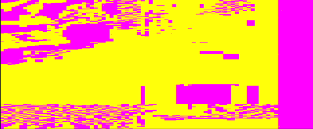
The key was using rpi_pixel_clock to trigger storing color in data and storing it in a single 90 bit register, then later using that as the horizontal line to display.
always @(posedge rpi_pixel_clock) begin

if(rpi_DEN)begin
      rpi_hc <= rpi_hc+1; // count horizontal pixels while DEN
      heart[(rpi_hc>>2)]<=b_in; // put color data in a 90 bit long register (using posedge rpi pixel clock already divides once)
end
else begin
rpi_hc <= 0;
end
end

...

always @(*)
begin

// first check if we're within vertical active video range
if (vc >= vbp && vc < vfp)
begin
// while we're within the active vertical range
// -----------------

if (hc >= hbp && hc < hfp)
begin
// while we're within the active horizontal range
// -----------------
pixel = heart[(hc>>3)]; // read a portion of the 90 bit long register

if (pixel == 1'b1) begin
//yellow
c2_symbol = 10'b1011110000; // red
c1_symbol = 10'b1011110000; // green
c0_symbol = 10'b0111110000; // blue
end
else begin
//magenta
c2_symbol = 10'b1011110000; // red
c1_symbol = 10'b0111110000; // green
c0_symbol = 10'b1011110000; // blue
end

end
*****
I’ve got rpi outputing 640 x 480 with this added to config.txt :
gpio=0-9=a2
gpio=12-17=a2
gpio=20-25=a2
gpio=26-27=a2

dtoverlay=dpi24
enable_dpi_lcd=1
display_default_lcd=1
dpi_group=2
dpi_mode=87
dpi_output_format=516118
dpi_timings=640 1 44 2 42 480 1 16 2 14 0 0 0 60 0 32000000 1
But when I try timng based on a 25MHz ,or 25.175MHz, clock at 640×480 it doesn’t work passing through the FPGA with a 25MHz pixel clock.
dpi_timings=640 1 16 96 48 480 1 10 2 33 0 0 0 60 0 25000000 1

#FPGA timings

#<hactive> 640
#<h_sync_polarity> 1
#<hfp> 16
#<hsync> 96
#<hbp> 48
#<vactive> 480
#<v_sync_polarity> 1
#<vfp> 10
#<vsync> 2
#<vbp> 33
#<n/a>
#<n/a>
#<n/a>
#<n/a>
#<n/a>
#<clock-frequency> 25000000
#<n/a>
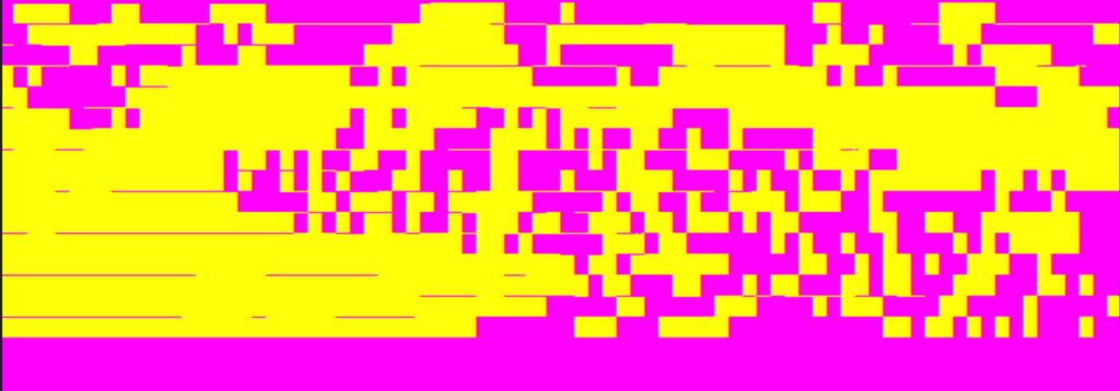
...

always @(posedge rpi_pixel_clock) begin


if(rpi_DEN && trig_record)begin
rpi_hc <= rpi_hc+1; // count horizontal pixels while DEN
heart[(rpi_hc>>2)]<=b_in; // put color data in a 90 bit long register (using posedge rpi pixel clock already divides once)
end

...

end
...

always @(posedge clk_x5) begin

if(vc[3:0] == 4'b1111) begin

trig_record <= 1;

end
else begin
trig_record <= 0;
end

...

end
*************
NO SCHOOL NEVERS BOARD:
- Removing things I don’t yet master with the FPGA like SD card, SRAM and rpi header. This will force me to learn to use the internal BRAM.
- Adding NO SCHOOL 24 logo
- Removing ground plane grid as it will interfere with text and soldering
- adding Cold Boot Sel Bits and a reset and a little table. This will be cool to learn how to make 4 small FPGA images that can be selected on restart.
- Added text to identify programming pins for instance.
- Changed the potentiometer so that it can be read by the FPGA
- Removed the comparator and changed to a cap + resistor bias + op amp follower setup so that analog input signal (via audio jack) can be read by FPGA.
- I tried to break out extra pins but just with small pads, but I also added 4 digital in pins.
- added quote !
- I’ve found leftover components at my lab which I will subtract from the Mouser inventory in order to order some fun parts like tiny 2pin DIP switches for the cold boot select and some op amps.
- I realized the VGA I ordered are male and mirrored. But I like the slim footprint (this way it doesn’t overhang over the edge of the board so much) so I ordered female slim and added to the board.
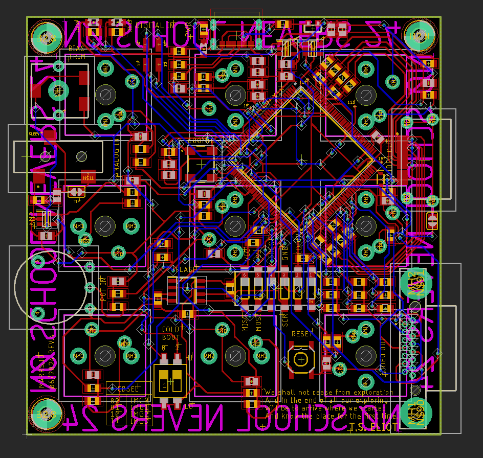
The plan for the 10h-13h, 14h-17h workshop is to start with basic VGA signal modification.
Start by cutting VGA cable and putting pins on a breadboard.
- What happens when you remove a color ? GND ? V or H sync ?
- How about switching colors ?
- Look at V and H sync on the oscilloscope
Let’s make waves with a function generator and see what they look like on screen.
- What do different frequencies look like on screen ?
- How about different wave types and duty cycles ?
What can we do with analog electronics ?
- A simple low-pass filter ?
- An amp
Get a second VGA video source.
- What happens when you mix colors from one source and colors from another source ?
- Which H and V signals do you send along to the screen ?
- Try using a potentiometer to mix two colors together, or fade a color out.
Introduction to logic:
- Let’s use a comparator to convert analog into ON or OFF
- Let’s try using an AND, OR and XOR with two video sources.
Introduction to FPGAs : The FPGA is reconfigurable logic which you can program to mess with video signals and respond to a tactile interface. To program the logic gates we use a Hardware Description Language (HDL) like verilog.
- Here’s how we generate a video signal using an FPGA
- Here’s how we generate some simple patterns
- Here’s how we make it react to button touches
The FPGA excels at doing things in parallel, with low latency, and consuming little power. In the world of video that means filters, basically what you can do with photoshop: spatial (2D, pixel based) : contrast, blur, edge detection, denoising, upsampling, downsampling. But this also as applied to a series of images (i.e. the same pixel location but at different moments in time) as in a video which is called temporal (or 3D) filtering. CPUs, by contrast, like an Arduino, have a series of instructions, and keep track of a program counter to know what line of code they are currently executing. (Yes GPUs can do things in parallel, but there aren’t GPUs we can solder ourselves and program in the same way.) FPGAs can be found in high-end networking equipment, scientific measurement equipement (like oscilloscopes and logic analyzers), hardware accelerators for certain types of AI, computer vision and FLIR heat cameras, and things sent into space (FPGAs are better at resisting radiation because of their architecture). They are good, flexible practice for ASICs, which are even faster but not reconfigurable and only cost effective when made on very large scales.
There are two types of digital logic we can implement in the FGPA : combinatorial and sequential. Combinatorial circuits are just like “raw” logic gates, reacting quickly to changing values and living in the near present. Combinatorial circuits are hard-wired together, they are limited mainly by the speed of electricity which is around that of light (1ns / foot). Sequential circuits, on the other hand, remember a past state, and therefore need some concept of discrete time like a clock ticking. A counter, which adds one each edge of a clock pulse until it rolls over, is an example of a sequential circuit.
The FPGA isn’t so much programmed as it is configured, by connecting all of it’s internal logic blocks together in various ways. (Yes, there are also specialized I/O blocks and BRAMs to store data, we’ll hopefully use these).
We’re going to assemble this kit that allows us to generate video (VGA or HDMI), and react to use button presses and knob turning. This could be done with an Arduino UNO, but it wouldn’t be able to do it as fast and as precisely (nor can it output HDMI). It’s primarily an FPGA development board, to get you started working with FPGAs, that has the addition of fun buttons. (Yes, FPGAs have been around for a while but they are still percolating into the DIY world and remain technically challenging for beginners).
****
I’ll need to prepare the following things for NO SCHOOL NEVERS 24:
- Four different images
that fit into the 1200 or so LUTs of the Lattice ICE40that just need to fit into the 4MB flash (each image is in kilobytes), that respond to 9 keys, 1 pot, music (and video?) in, and VGA out (primarily) and HDMI out. - 18 kits, with all necessary components, and PCBs with at least FPGA, power and programming and debugging related components, soldered.
- The VGA workshop materials : VGA cables, breadboards, jumpers, passive components, logic chips, pots + oscilloscope, function generator.
- A talk that could include a chapter on video hardware experiments.
****
I’m working on getting the four demo codes reacting to buttons, potentiometer and audio in. I’ve had various problems, mostly due to mysterious VGA behaviour only outputting v and h sync when a certain buttons is pushed, for instance, and perhaps (haven’t confirmed this) IceCube2 having difficulty identifying the top module when there are multiple .v files.
I have combined the random, tempo and sine files into the principle vga_test file and looked at the VGA signals with the microscope to debug.
Some codes, like random walk or grid of forms + noise, would be easier with a screen buffer.
So far the coolest thing I have is this automatic rectangle color composition, but I haven’t been able to make it interactive in any way :
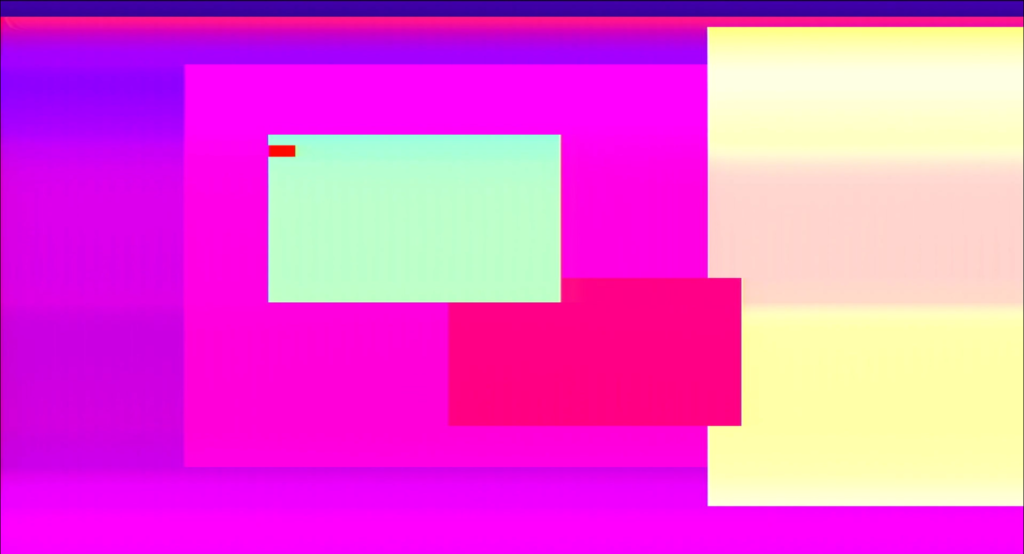
I have learned that the best way to switch between different form generating codes is just to run them all in parallel and then select which of them you want to use like with a MUX :
// CONDITIONS

wire a,b,c,d;
reg condition;

assign a = ((bit_or[random_number_2[3:0]] == 1) || (bit_or[random_number_6[3:0]] == 0)) ? 1 : 0;
assign b = ((h_count % 100 < (random_number_0[9:0] % (100+data_out))) && (v_count % 100 < (random_number_1[9:0] % (100-data_out)))) ? 1 : 0;
assign c = ((h_count % 100 < random_number_0[9:0] % 100) && (v_count % 100 < random_number_1[9:0] % 100)) ? 1 : 0;
assign d = ((out_bit[random_number_2[3:0]] == 1) || (out_bit[random_number_6[3:0]] == 0)) ? 1 : 0;

//priority encoder
always @(*) begin
casez(key)
9'b1????????: condition = a;
9'b?1???????: condition = b;
9'b??1??????: condition = c;
9'b???1?????: condition = d;
9'b????1????: condition = a;
9'b?????1???: condition = b;
9'b??????1??: condition = c;
9'b???????1?: condition = d;
9'b????????1: condition = a;
default: condition = a;
endcase
end
Apparently casez can be a dangerous thing to use in verilog though (see https://www.verilogpro.com/verilog-case-casez-casex/)…
****
I’ve got a simple sine wave demo setup using a LUT :
reg [4:0] addr;
reg [7:0] data;
reg [7:0] data_out;
always@(addr) begin
case (addr)

0 : data = 0;
1 : data = 16;
2 : data = 31;
3 : data = 45;
4 : data = 58;
5 : data = 67;
6 : data = 74;
7 : data = 77;
8 : data = 77;
9 : data = 74;
10 : data = 67;
11 : data = 58;
12 : data = 45;
13 : data = 31;
14 : data = 16;
15 : data = 0;
16 : data = -16;
17 : data = -31;
18 : data = -45;
19 : data = -58;
20 : data = -67;
21 : data = -74;
22 : data = -77;
23 : data = -77;
24 : data = -74;
25 : data = -67;
26 : data = -58;
27 : data = -45;
28 : data = -31;
29 : data = -16;
default : data = 0;
endcase
end

reg[25:0] div_cntr1;
reg[25:0] div_cntr2;
reg half_sec_pulse;

always@(posedge clk_in)
begin
div_cntr1 <= div_cntr1 + 1;
if (div_cntr1 == 0)
if (div_cntr2 == 0)
begin
div_cntr2 <= 0;
half_sec_pulse <= 1;
end
else
div_cntr2 <= div_cntr2 + 1;
else
half_sec_pulse <= 0;

end


always @(posedge half_sec_pulse) begin

data_out <= data;
addr <= addr + 1;
if(addr == 29)
addr <= 0;

end
*****
Synplify Pro by Lattice lets you see the RTL :
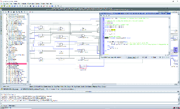
You can also simulate verilog code live in browser (https://digitaljs.tilk.eu/):
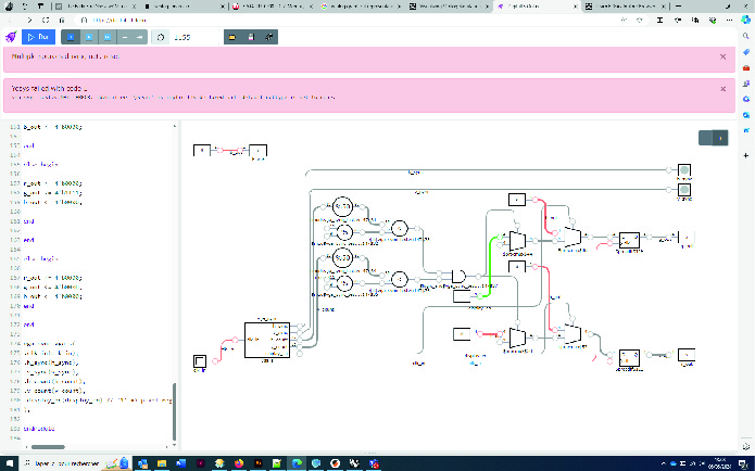
Check out how pretty these FPGA layouts are :
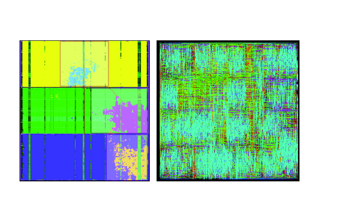
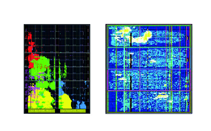
FFGlitch that Rémi told me about :
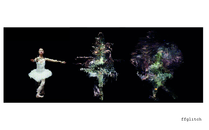
*****
Project summary of last 2 years so far :
So far in this project I’ve worked with video in a naive, hands-on way by taking a stream and modifying it and recording it directly, without processing it first and taking into account the framing, into memory. I’ve learned to use higher level programs like Processing to generate simple patterns. I’ve learned how to configure digital circuits with FPGAs to generate video. On the product design side, I’ve practiced designing PCBs with different interfaces, worked with color and black and white, and experimented with SD cards, HDMI out, and rpi DPI for a future product idea. I’m starting to learn how to process incoming video with the FPGA and I can display an image stored in ROM on-screen but next I’d like to display dynamic memory on screen as a screen buffer (either using cascaded internal BRAM or external SRAM). Then I could start leaving traces of past frames as is fun in Processing, and blitting (changing the memory contents “directly” at a memory level) and seeing the result on the screen directly. Next would come spatial and temporal filtering at a hardware level.
I am starting to wonder if my home is DIY not design. I don’t know if I want to sell niche designy synth objects to bobos for 600 euros, I think I’d prefer to make inexpensive open source kits and workshops.
****
The title of the NO SCHOOL event is NØ VIDEO GLITCH FPGA, so where are my glitches ?! N.B. Glitch might come from the German word glitschen ‘to slip’ and the Yiddish word glitshn ‘to slide, to skid’.
- The HDMI DC imbalanced glitch
- Desynchronized and zoomed out video
- messing with the functioning of the recording module creating choppy scrabled recordings
- Images being sampled at such a ridiculously low rate that one byte represents a whole image frozen on screen
- ghost recordings when recording parallel tracks in SRAM
******
Met a cool NY-based, sound engineer named Noah Ross who gave me some cool references :
The metaphore of the cone of the possible with a tool, some offering more exploration and failure than others.
Chase bliss – Generation Loss (https://www.chasebliss.eu/generation-loss-mkii) They explain that they took apart VCRs and other tape media to create this device which allows for precise calibration of tape effects. This connects with what Noah was describing when talking about tools that let you change the heartbeat of the machine, like letting you alter one part of a digestive tract without knowing what impact it will have on the end output.
Noah also mentioned a sampler that takes varying sizes of mini samples from a sample in different looping and sub sample selections dynamically.
I’m really impressed with the text they have developed to describe the functionality of these :
Spatial chemistry, Living landscapes, Spectral surprises.
Chord synths with buttons for chords :
This Monome grid interface (https://monome.org/docs/grid/) which lets you interact with an array of samples by moving through them in different patterns :

Monome teletype (https://monome.org/docs/teletype/), an algorithmic ecosystem where you code your own triggers for events :
An Oil can delay, which can have a knob for “viscosity” ! I don’t understand how this works yet :
******
COLD BOOT process :
In diamond Programmer go to Design > Utilities > Deployment Tool then select External Memory and Advanced SPI Flash
…
…and then select a binary file :
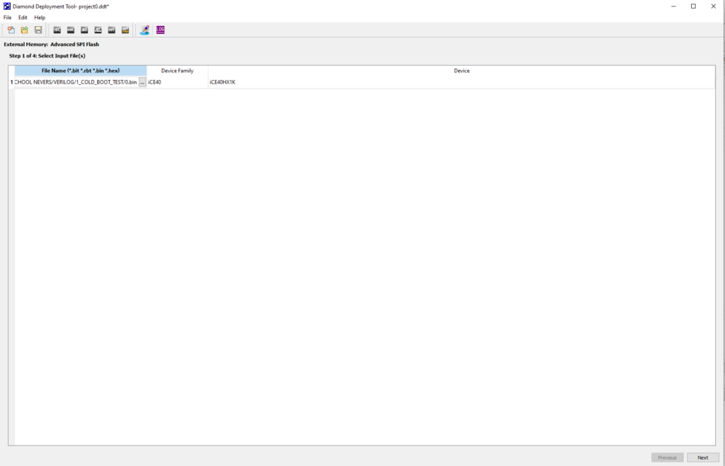
Change the SPI Flash Size to 32Mb and then select the Multiple Boot binary files (Ice erases any folders you make in its output file) :
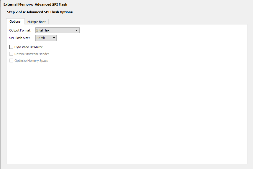
The last step is to generate the mcs file.
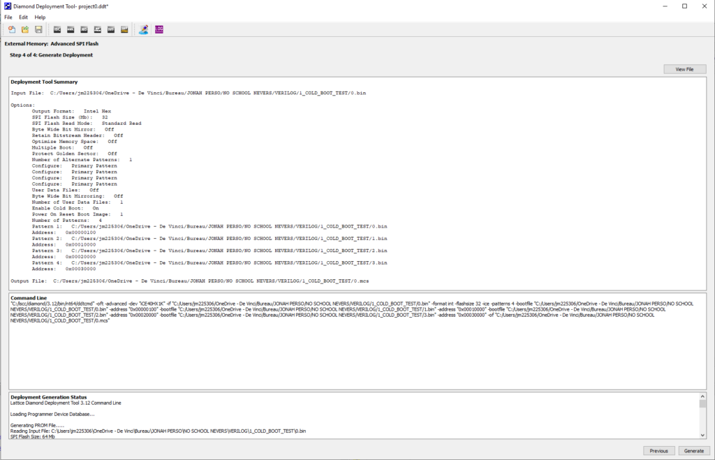
I tested with different speeds of LED blinking and it works with the reset button and the dip switch.
****
![]()
https://en.wikipedia.org/wiki/Image_scaling
****
FEEDBACK FROM PRACTICE WORKSHOP :
print an image of what to solder where, numbers of each component needed, pieces of paper with tape and pens, tweezers, soldering iron, solder, flux
solder everything that needs a microscope !
Intro to SMD soldering, tacking, boards to practice soldering on.
have other programs open to do simulate and show the floor
only talk about stuff that is directly applicable in the workshop, with an eye to the finality (why am I soldering this specific thing). No theory, just practice
to solder 12 things takes a while !!! The buttons are the coolest.
to cut into mini projects with a mini success at the end.
Should talk about why it is worth learning hardware nowadays.
how to make it so they can use it, reprogram it,
perhaps let them code something super super simple with you, like you push this button and this color appears on screen ! Prepare a code where they do tiny change and can see the effect.
BE LESS AMBITIOUS for this workshop, it would take a whole week to do what you have planned dude. You could imagine a tiny thing with four buttons and an HDMI out and they do a code that changes the color that appears on screen, or sents a bitmap.
explain how HDMI and/or VGA formats work ?
Perhaps the best demonstration of what the FPGA can do is to have a camera in and show if filtering the live input and outputting that to HDMI ?
what is the minimum ? (HDMI resistors + just the keys without resistors or caps?)
intro to electronics ? intro to digital electronics ? Intro to logic ? Intro to binary ? Into to FPGA ??
Have already prepared rock solid codes which work 100% and are already loaded onto the boards on organized with correct pcf + v + auxillary files
Have the four codes prepped and reacting to music + key touch + potentiometer !
Thinking back to things I’ve learned from Arduino and Processing workshops of the past : Go to the simplest/easiest + coolest things as fast as possible. Stay away from difficult tech stuff with little reward and give them an opportunity to be creative fast.
****
To do in the next 3 weeks :
Finish soldering the 17 boards, everything except knobs, buttons and audio-in jack. (necessary to solder the 10K + 1uF for buttons or just 1K ? Should solder HDMI as I won’t be using it in the workshop?)
Develop 4 different VGA (+ HDMI?) codes which react to pot, 9 keys, and audio in.
Make website explaining how to upload new code with rpi + open source toolchain.
Gather parts for hands-on VGA portion.
Finish one complete kit to be able to show what it can do.
Assemble the parts in bags with printouts.
*****
Tommy sent me this awesome shader tutorial series : https://thebookofshaders.com/
- Algorithmic drawing
- Generative designs
Then there is a chapter on Image processing :
- Textures (https://en.wikipedia.org/wiki/Texture_mapping)
- Image operations (https://www.cse.unr.edu/~bebis/CS791E/Notes/PointProcess.pdf)
- Kernel convolutions (https://en.wikipedia.org/wiki/Kernel_(image_processing))
- Filters
- Others effects
I think I’m gradually understqnding what FFT is thanks to this text from (https://en.wikipedia.org/wiki/Digital_image_processing) :
“Filtering can be performed by…masking specific frequency regions in the frequency (Fourier) domain”
Also new to me is the idea of modifying a historigram https://en.wikipedia.org/wiki/Histogram_equalization
Also watched a video on Touch Designer and understood what all the hype is about ! Visual programming like with Grasshopper but can do Processing video and image transformations really didactically.
Blender is also more and more powerful and popular of course for mesh and texture editing. It can also do animation / video.
*****
CONWAY’S LAW :
Any organization that designs a system (defined broadly) will produce a design whose structure is a copy of the organization’s communication structure.
OPEN SOURCE primer from Paul:
FSFE https://media.fsfe.org/w/p/9gYSyoEYggsqBExLWjRejL?playlistPosition=4&resume=true
The Fuz hackerspace manifesto : https://fuz.re/
Great teardown videos from the long running EEV blog. Fascinating to see different eras of technology (through hole, SMD, flexible circuits, varying degrees of integration), the easter eggs (signatures of Apple employees on the inside of the metal casing, Amiga computer chips named after girlfriends), the bodges (reusing a film camera body for the first digital SLR, jumper wires, last minute added boards), the unusual and mysterious decisions, the design for multiple versions of a product including multiple boards that are likely to be redesigned at different frequencies, the different ages of boards and parts from inside the same device (by looking at the year and week codes), all the work to shield different things inside, the different between a cheap product that was mass produced and a smaller scale high end product on the inside, the attempts to obfuscate or make it difficult to open something up, the efficient and ingenious solutions vs the cost effective solutions, the typical points of failure (battery leaks, mechanical failure of plugs), varying soldering and board cleanliness quality, the use of plastic films and sheet metal in conjunction with boards, the 3D integration challenge of small portable consumer electronics that integrate moving parts; multiple boards with connectors and optics, serviceability considerations, moment where space was wasted, exotic and rare obsolete technologies (late CRT pocket monitor), some sublime documentation with hand drawn systems diagrams and plenty of information (https://www.youtube.com/watch?v=tQyX3F4ggM8).