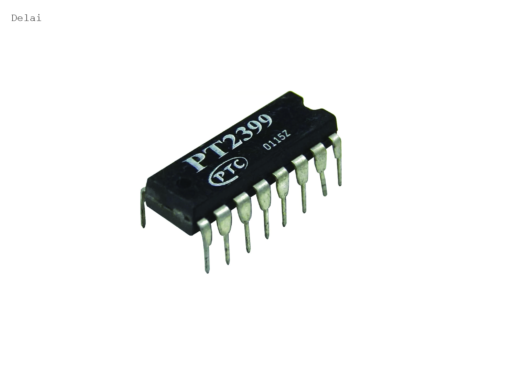
Karl and I are planning to work on other sides of the ocean on this project together. Karl will continue working on the overall collection and interaction of the modules, I’ll work on prototyping one module at a time. We hope to find a collection of modules that are cool and to see which modules we can make ourselves easily and which we need to buy chips for (such as delay).
The plan is to converge on a prototype with Karl in simulation and me in prototyping. I can mail prototypes for Karl to try in Vancouver and once we have a basic prototype we can move on to test different interfaces, and begin to think about the kit and the cost of the machine. We’re aiming currently for an intermediate level device.
We want to document things well and possibly even produce a collection of music from this device made by Karl’s artist friends. Our collaboration accross the ocean could be a theme in a video we make of the project, for instance.
*******
I am colaborating with Karl Fousek, https://karlfousek.com/, a fantastic Vancouver based sound artist. He proposed the following synth prototype:
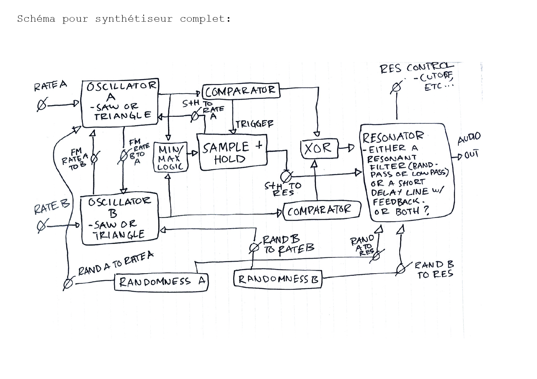
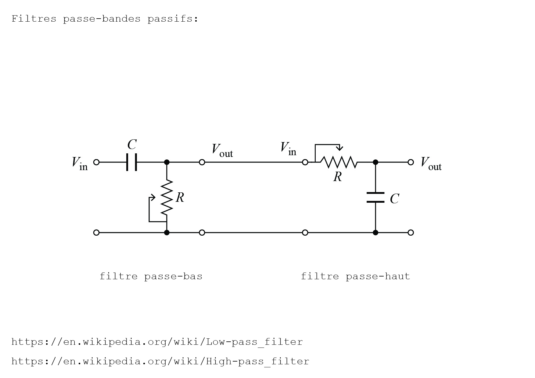
Breaking this design up into smaller bits, I have the following designs. They are inspired also by the tinybits modular synth design found here: http://d2q6sbo7w75ef4.cloudfront.net/SYNTH-booklet.pdf
*****************
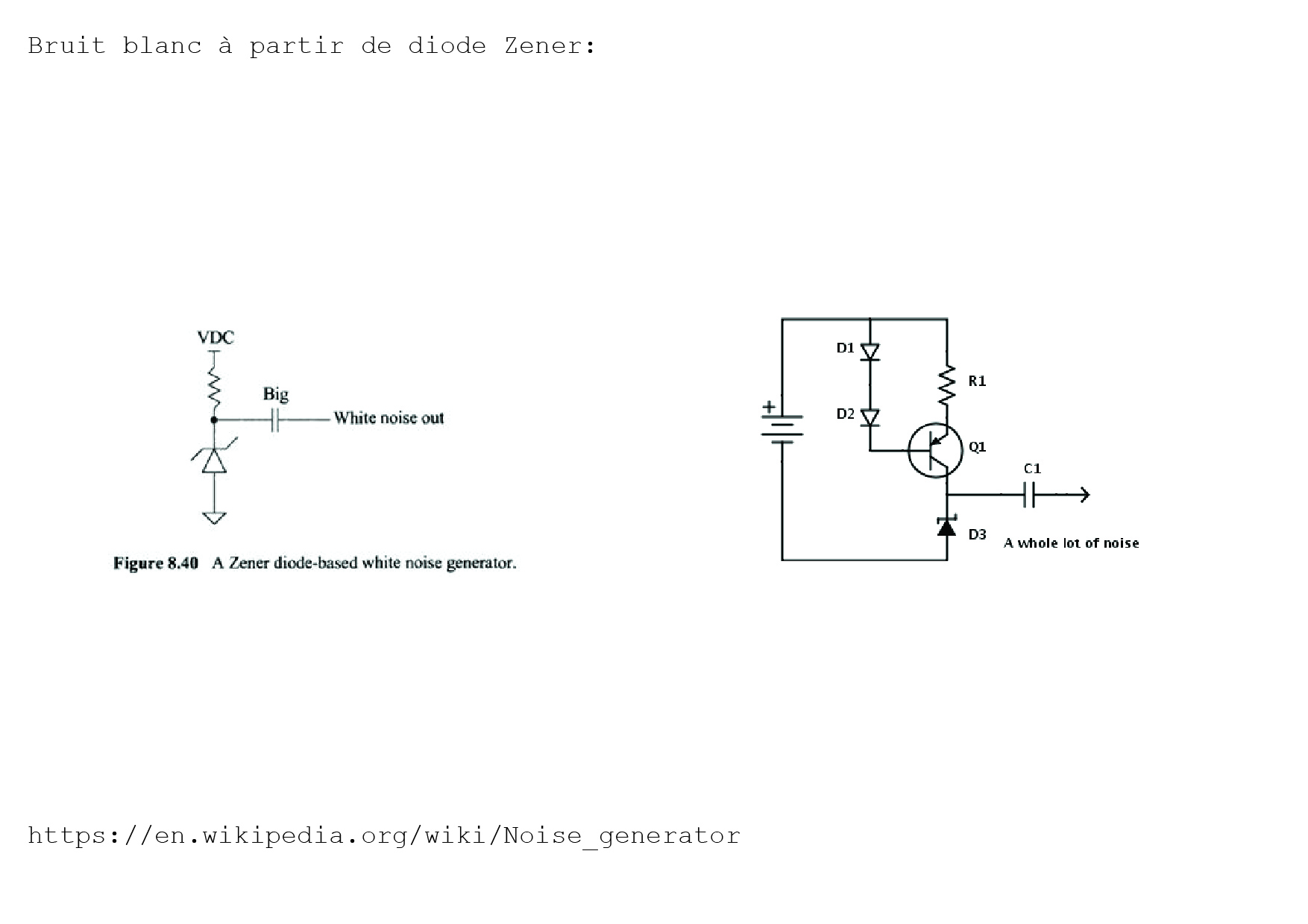
NOISE GENERATION
I tried this but it didn’t work with my 3.3V zener…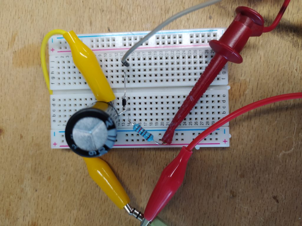
No dice either! Two more simplish options:

I could just generate noise with a microchip: https://forum.arduino.cc/index.php?topic=617302.0
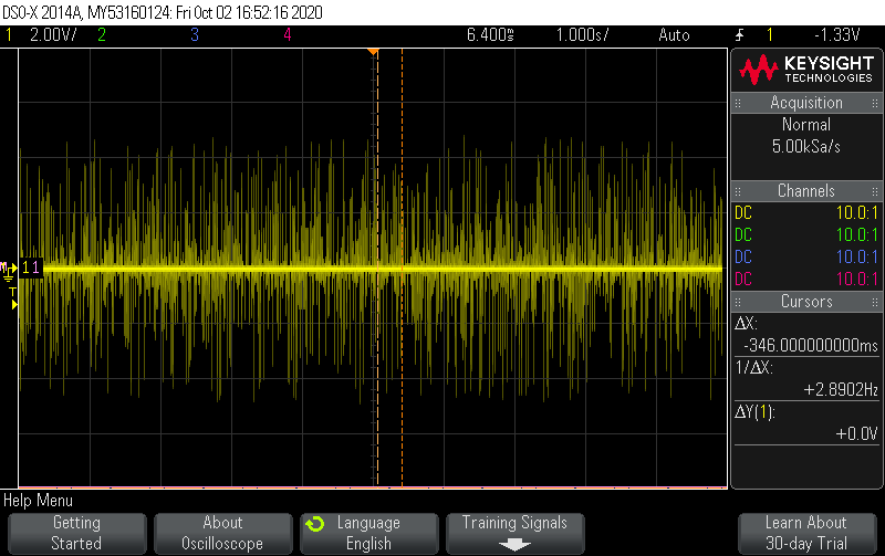
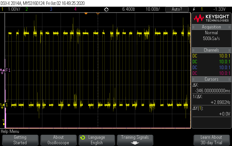
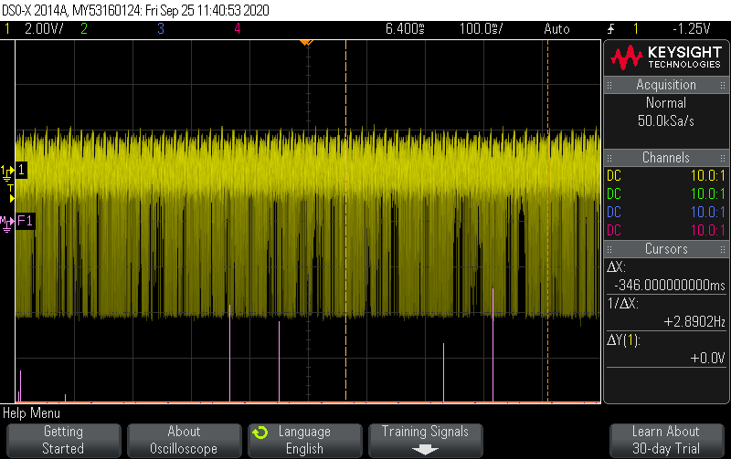
I put this through a high pass filter and here are the results:
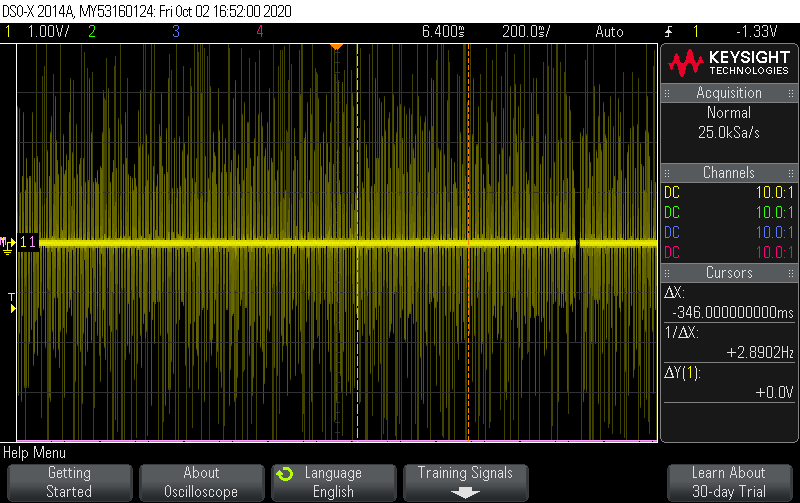
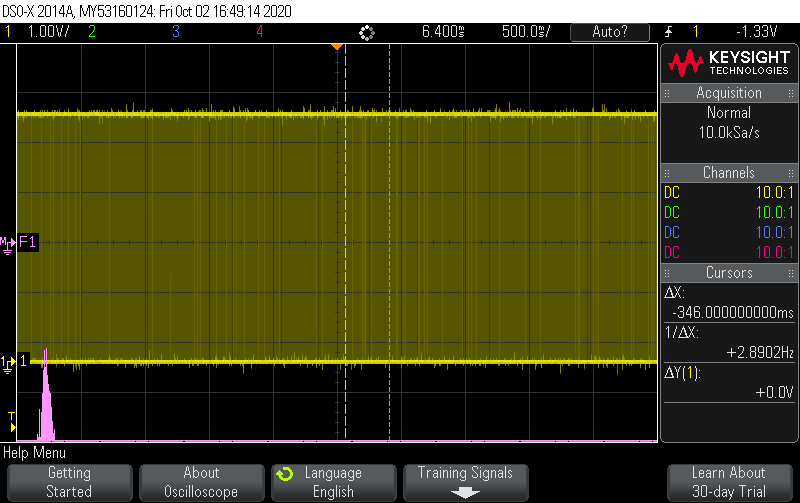
This is what the signal looks like before being put through the filter:
****
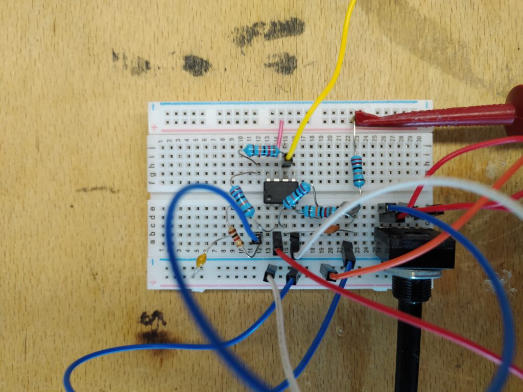
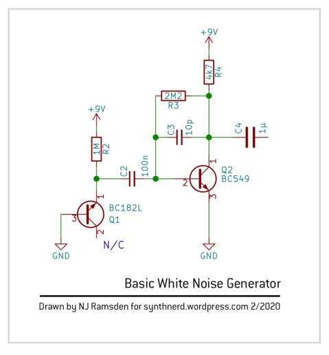
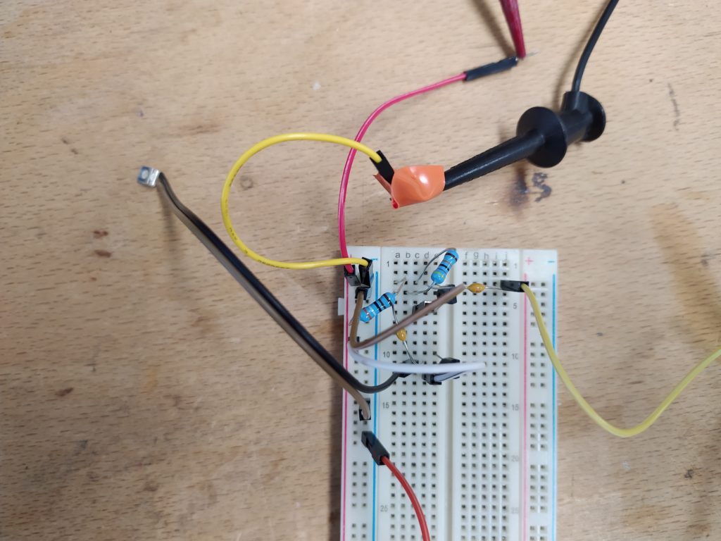
We have noise! I built the circuit from this site: http://freenrg.info/Physics/Scalar_Vector_Pot_And_Rick_Andersen/Rick_Andersen_Noisegen.htm
I used a 1M trim pot in place of the 470K to tune the noise and used 0.1uF caps in place of 0.047uF, PN2222As in place of 3904, and a 3.9K instead of a 4.7K:
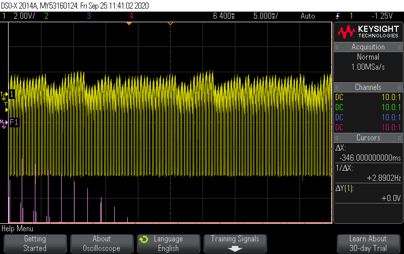
Here’s what is sounds like:
************************
~~~~~~~~~~~~~~~~~
Sample and hold:
https://www.ti.com/product/LF398-N
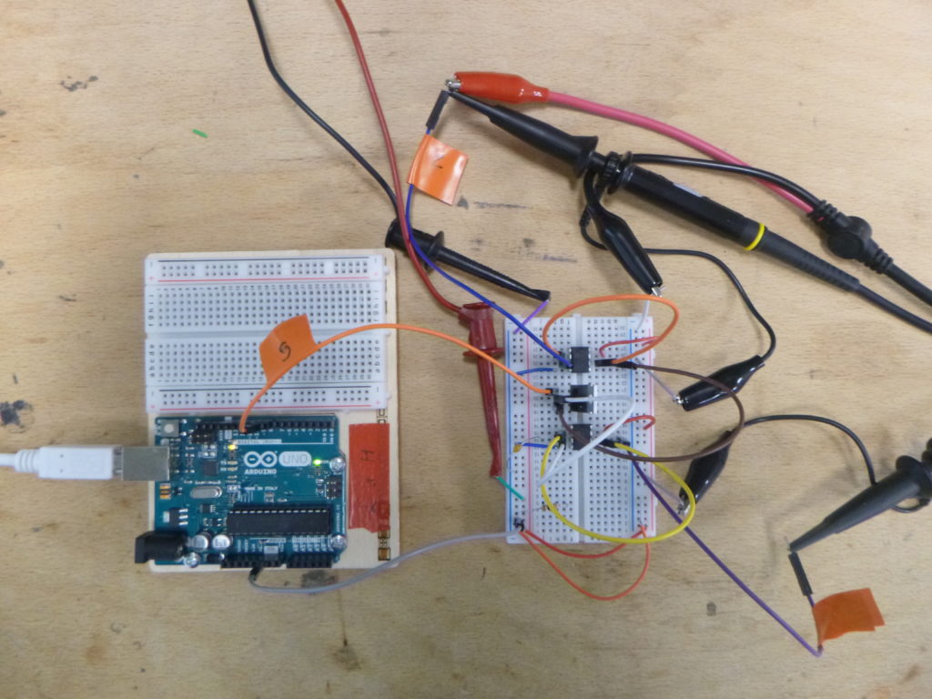
Which is the circuit below (minus the comparator, I’m using Arduino to generate a pulse every 1ms of 1ms duration):
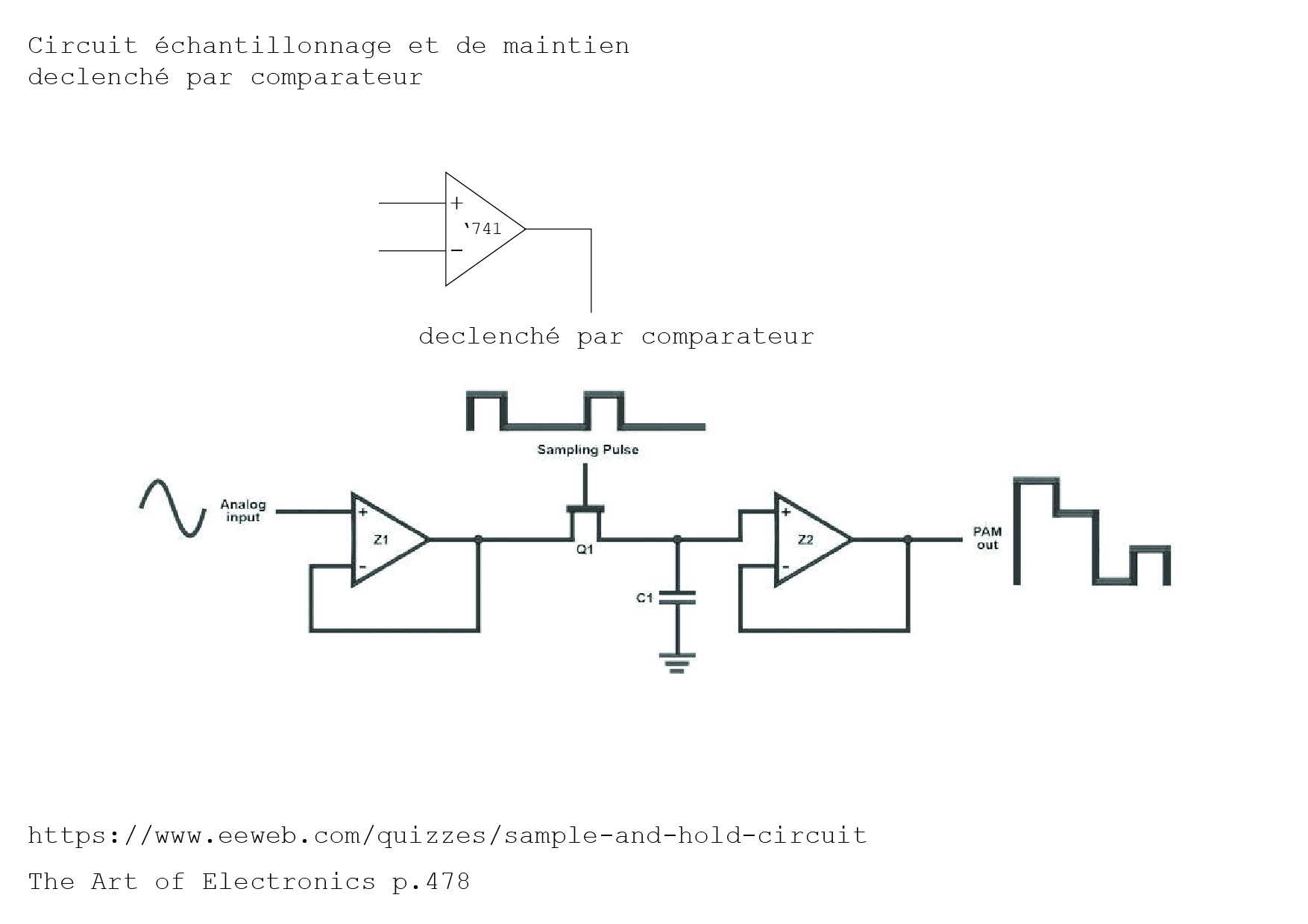
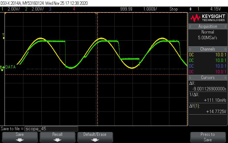
I’m using two MCP6241 op amps (I tried 741s but they don’t go rail to rail which I think was the issue) powered with 5V. I kind of arbitrarily picked 0.1uF as the C. I’m using an IRF 740. The signal generator is outputing a sine wave with 2V amplitute and a 1V offset.
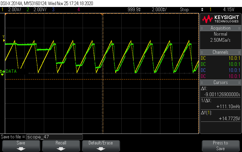
Here are more screep caps :
With a triangle wave:
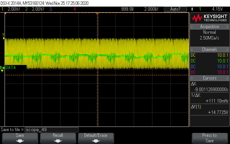
With noise:
Again with a sine:
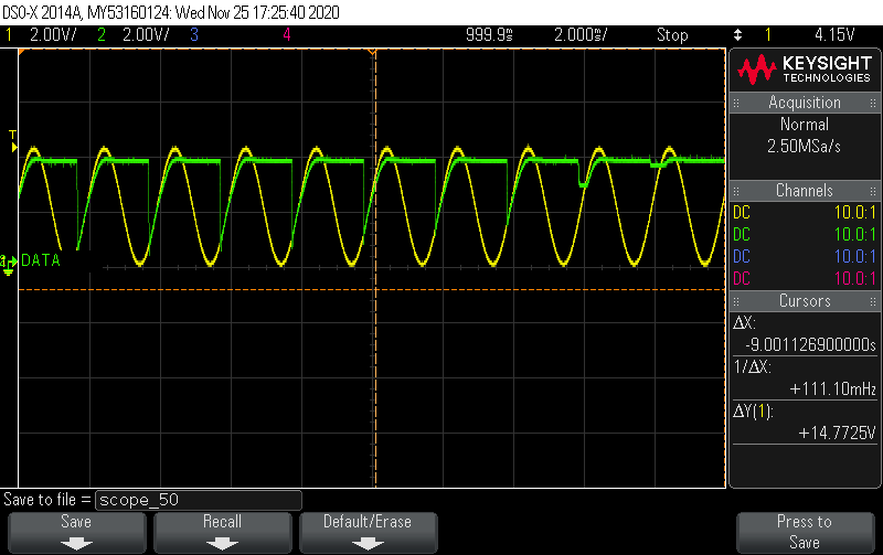
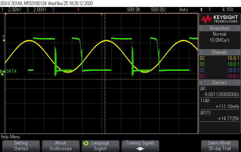
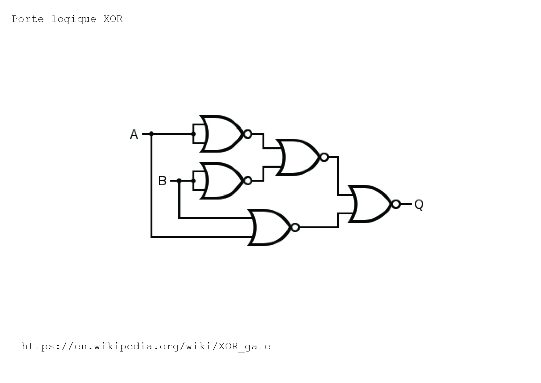
XOR:
Using an 74LS86 with an arduino generated square wave every millisecond and a sine wave from the function generator, fun and easy!
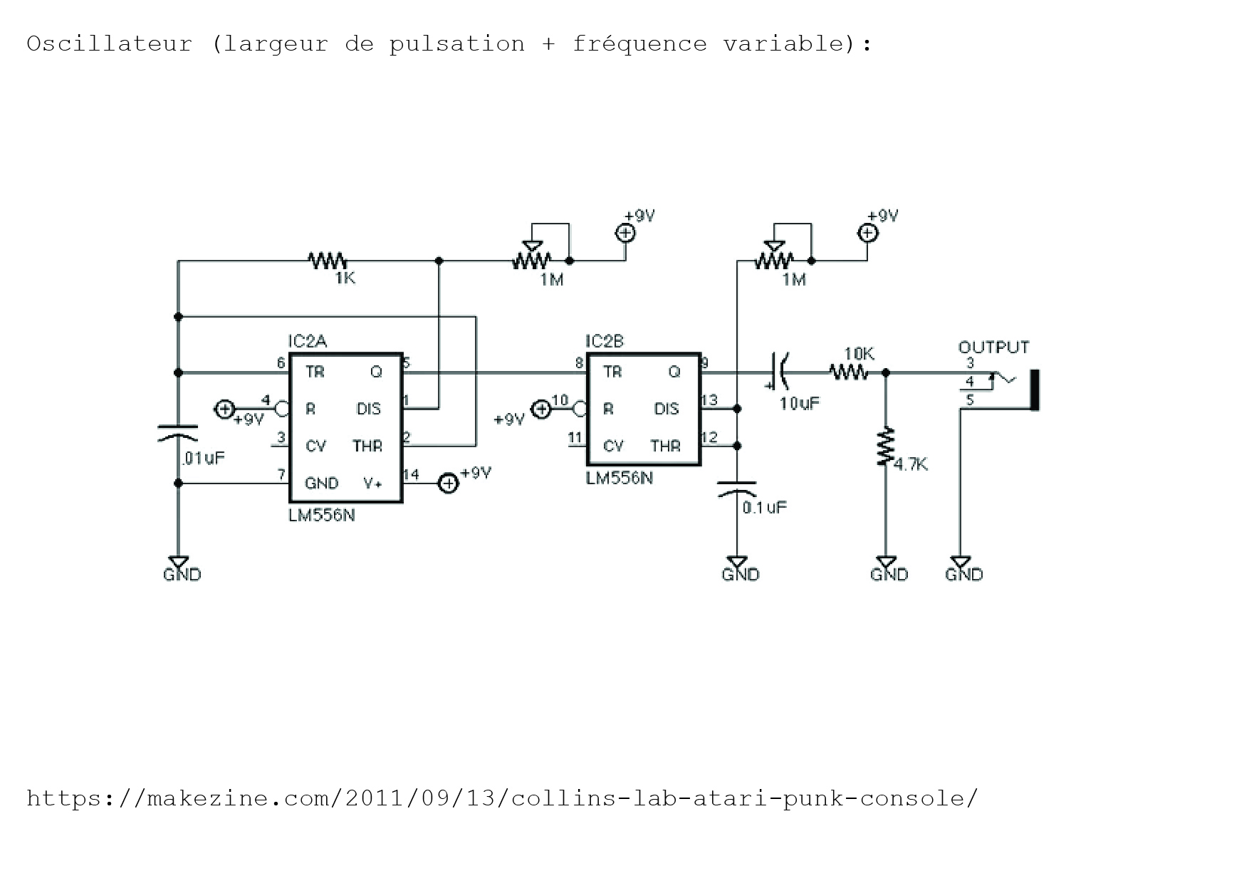
PART I: OSCILLATOR
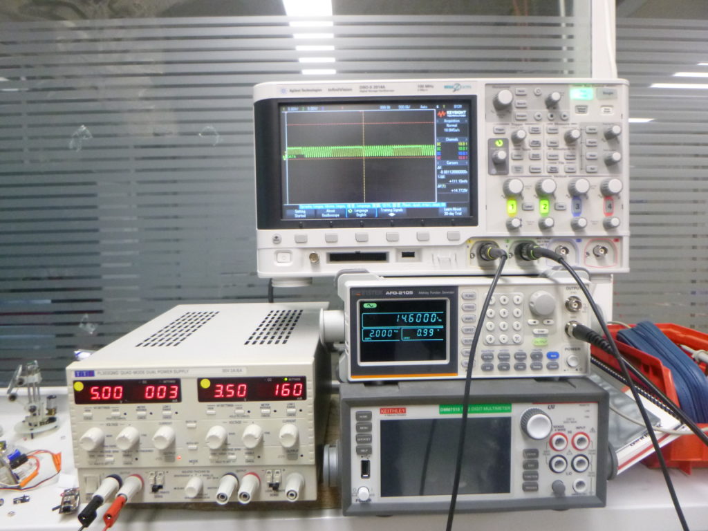
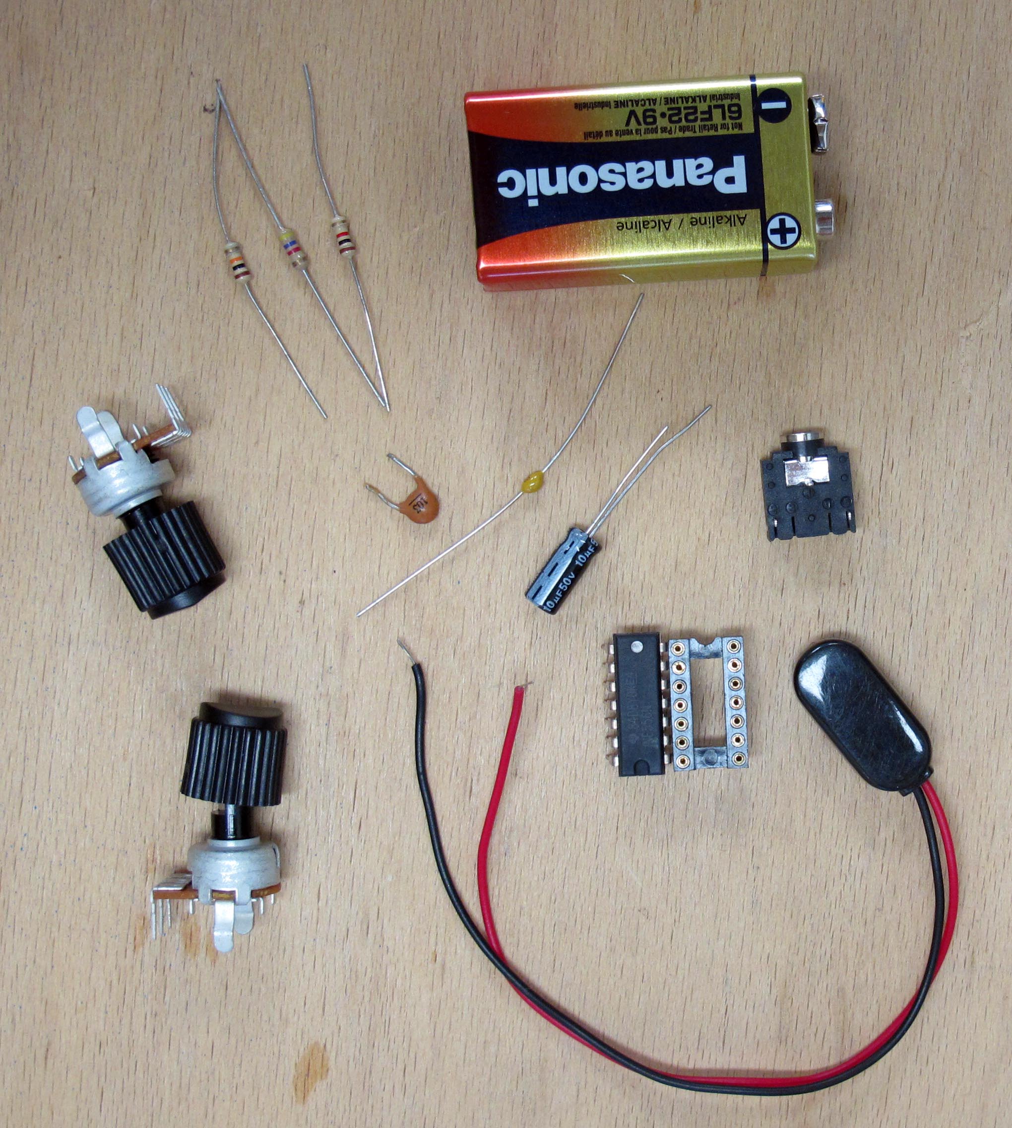
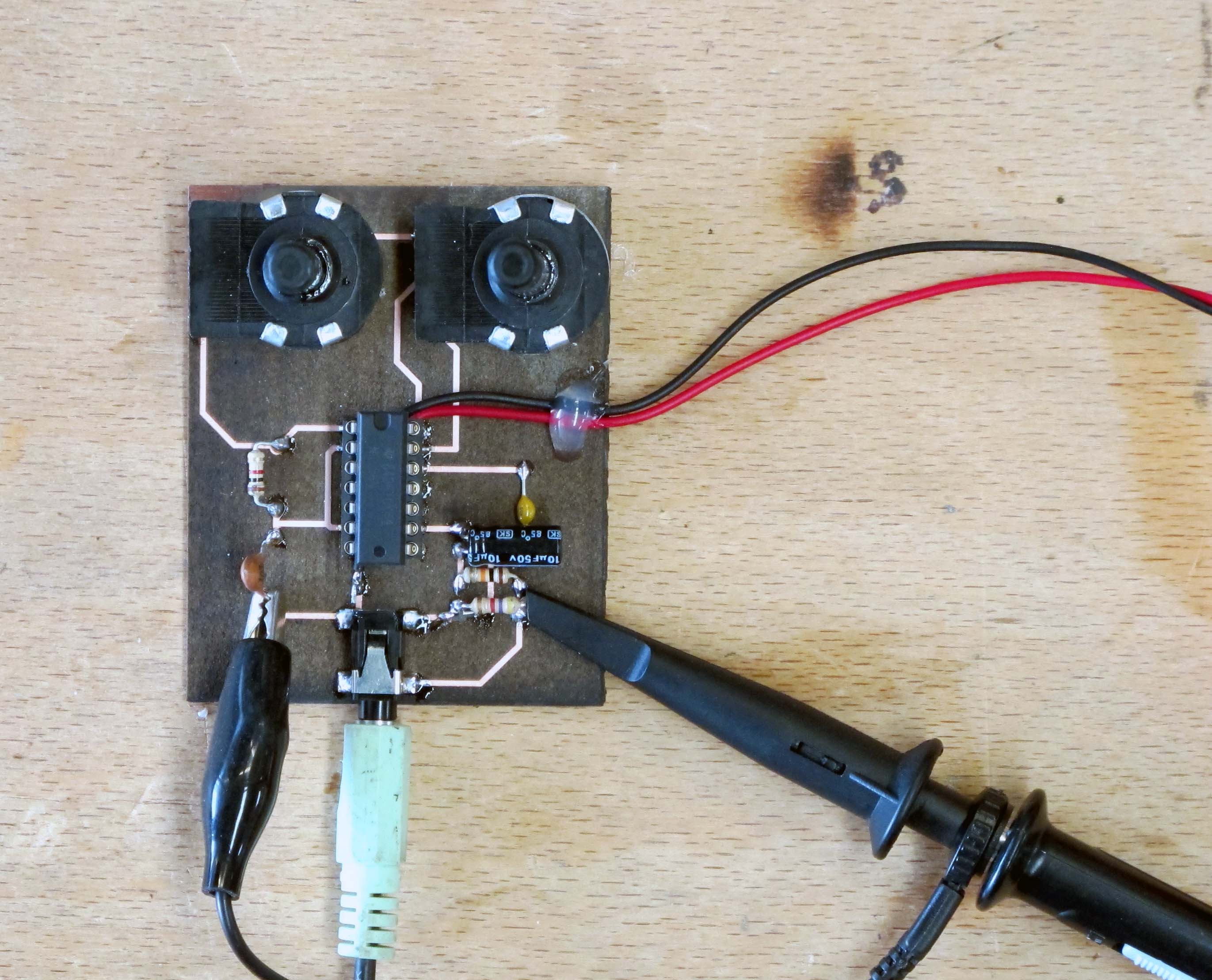
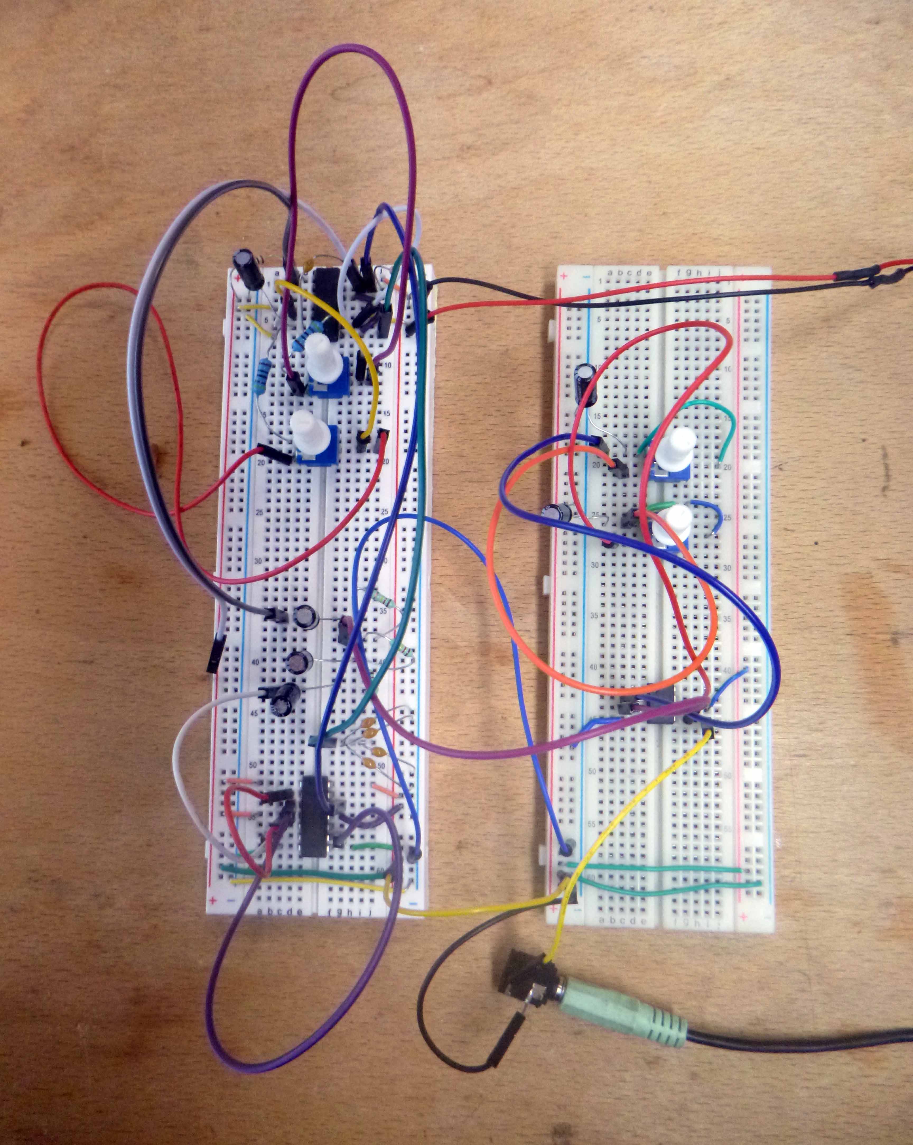
Checking to make sure everything works on breadboard first!
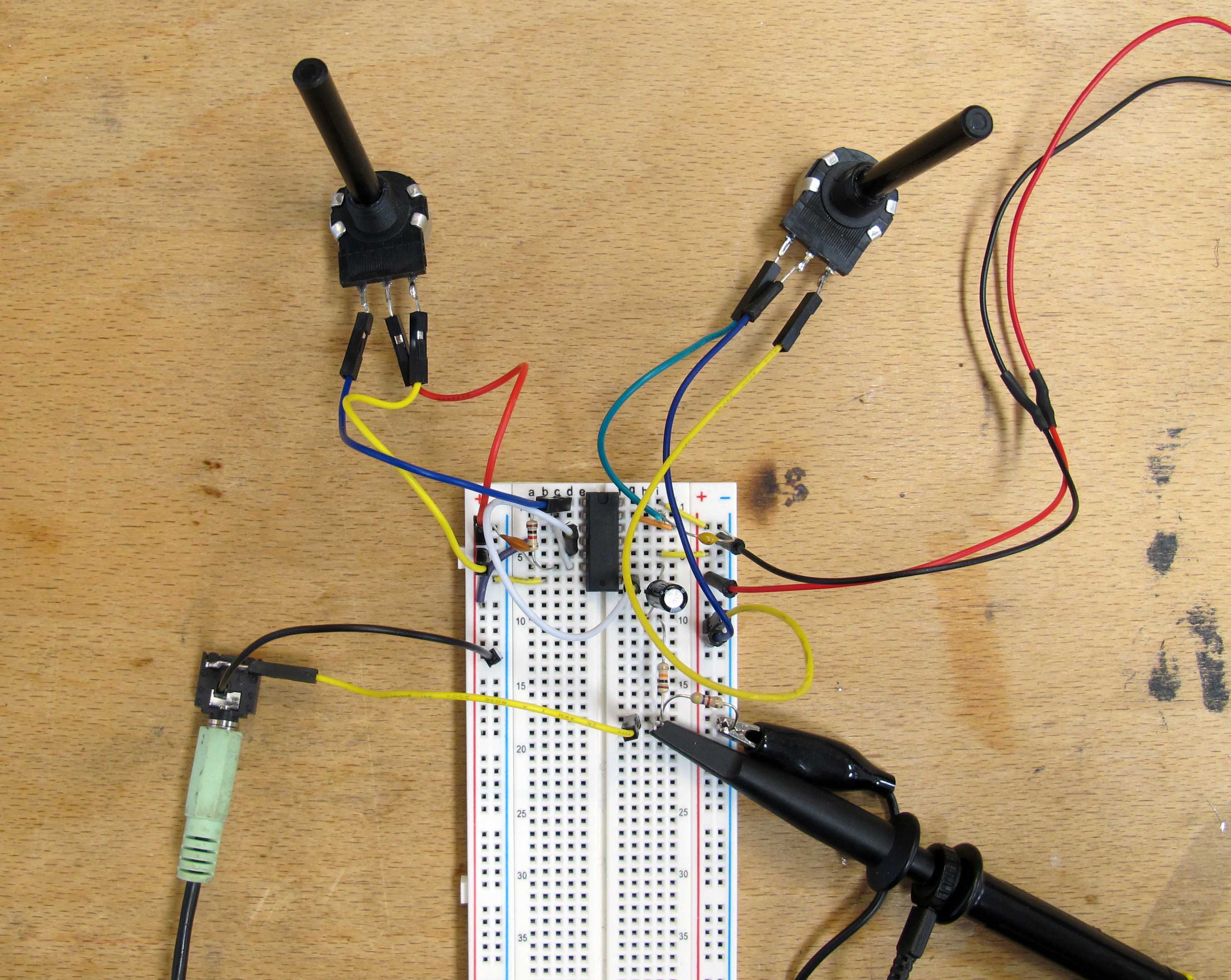
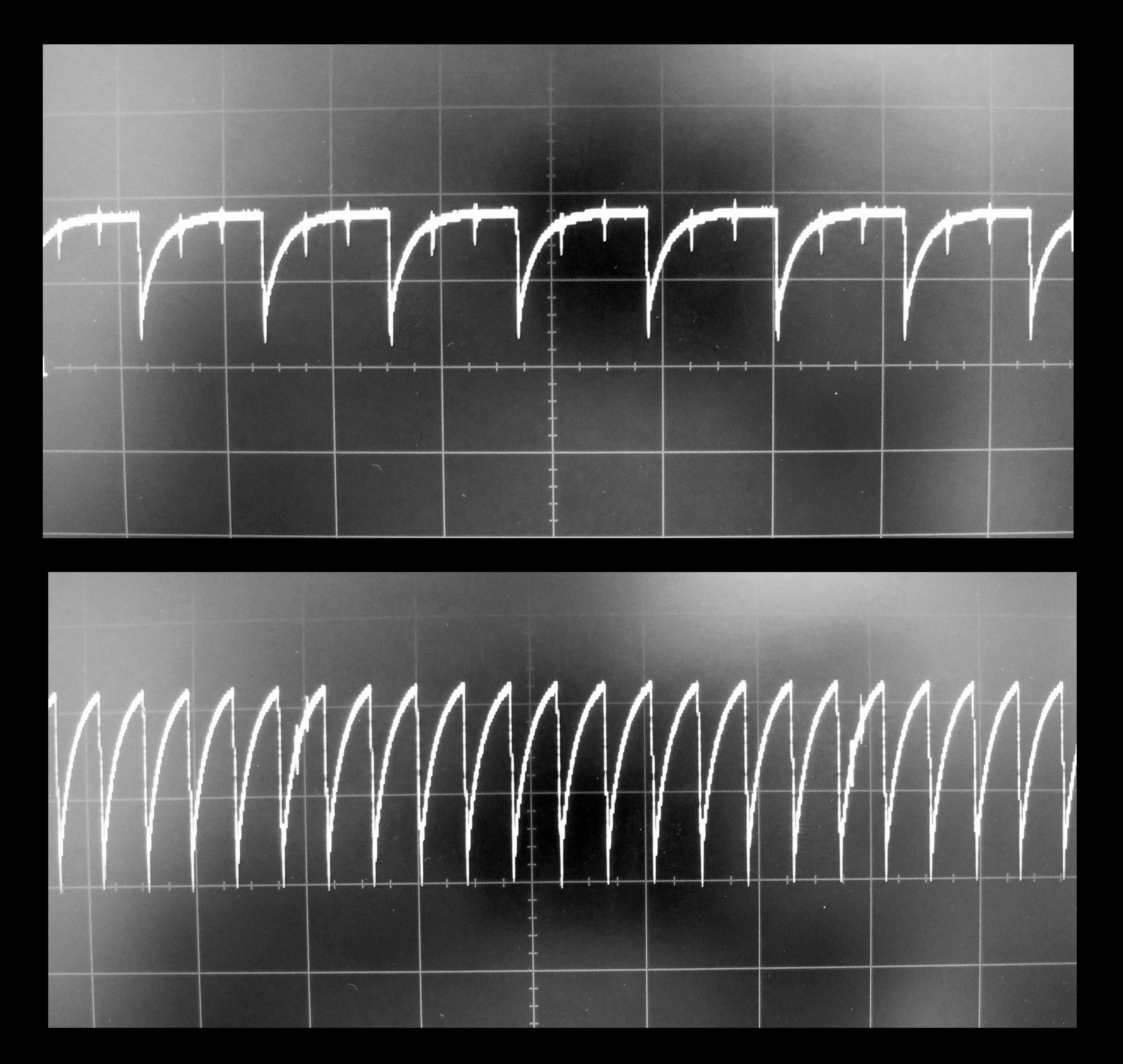
Synth on the oscilloscope:
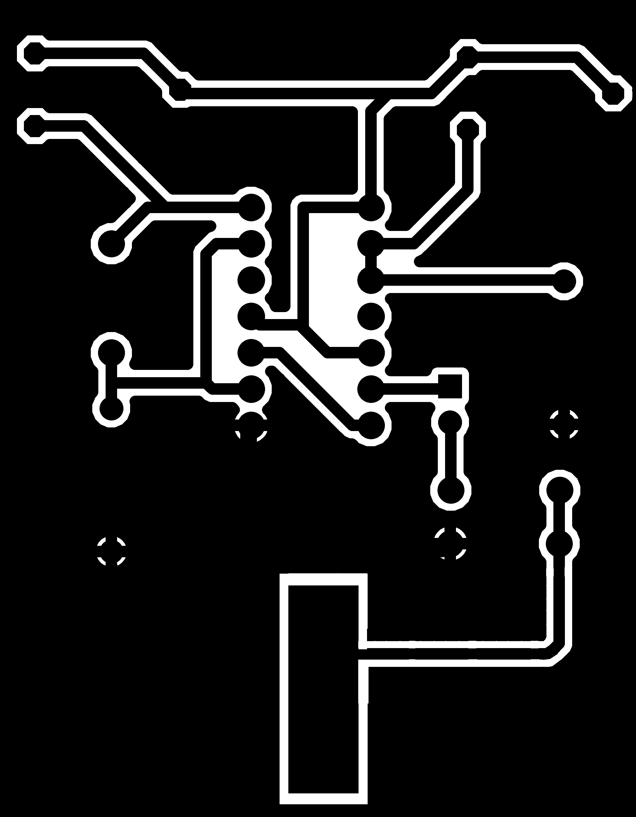
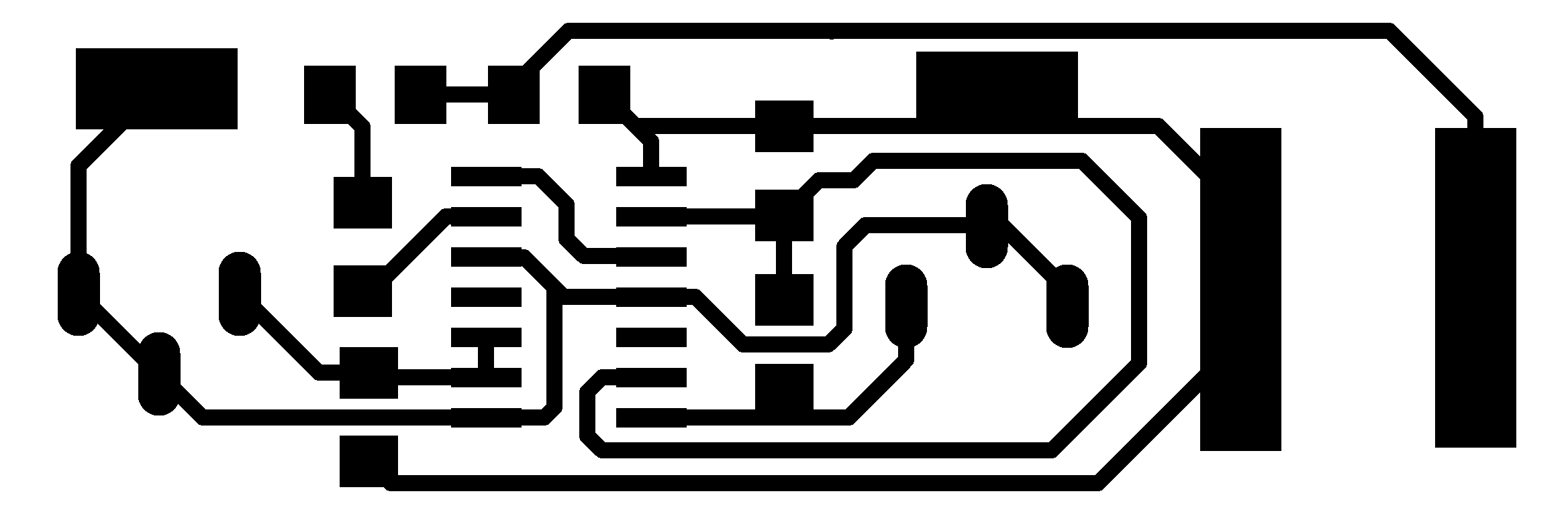
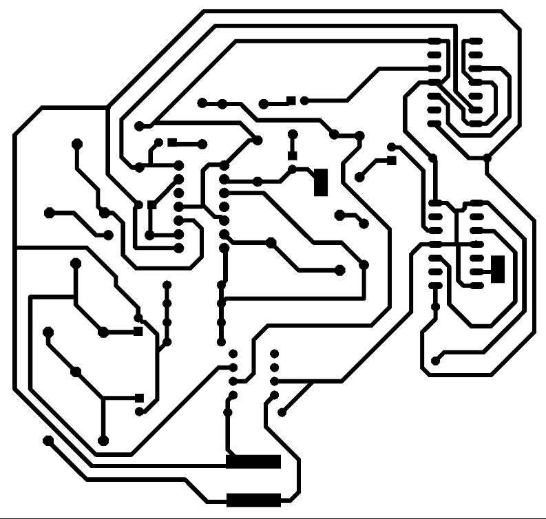
I have taken the Atari Punk Console design and made it quickly in Eagle:
This design had two main flaws:
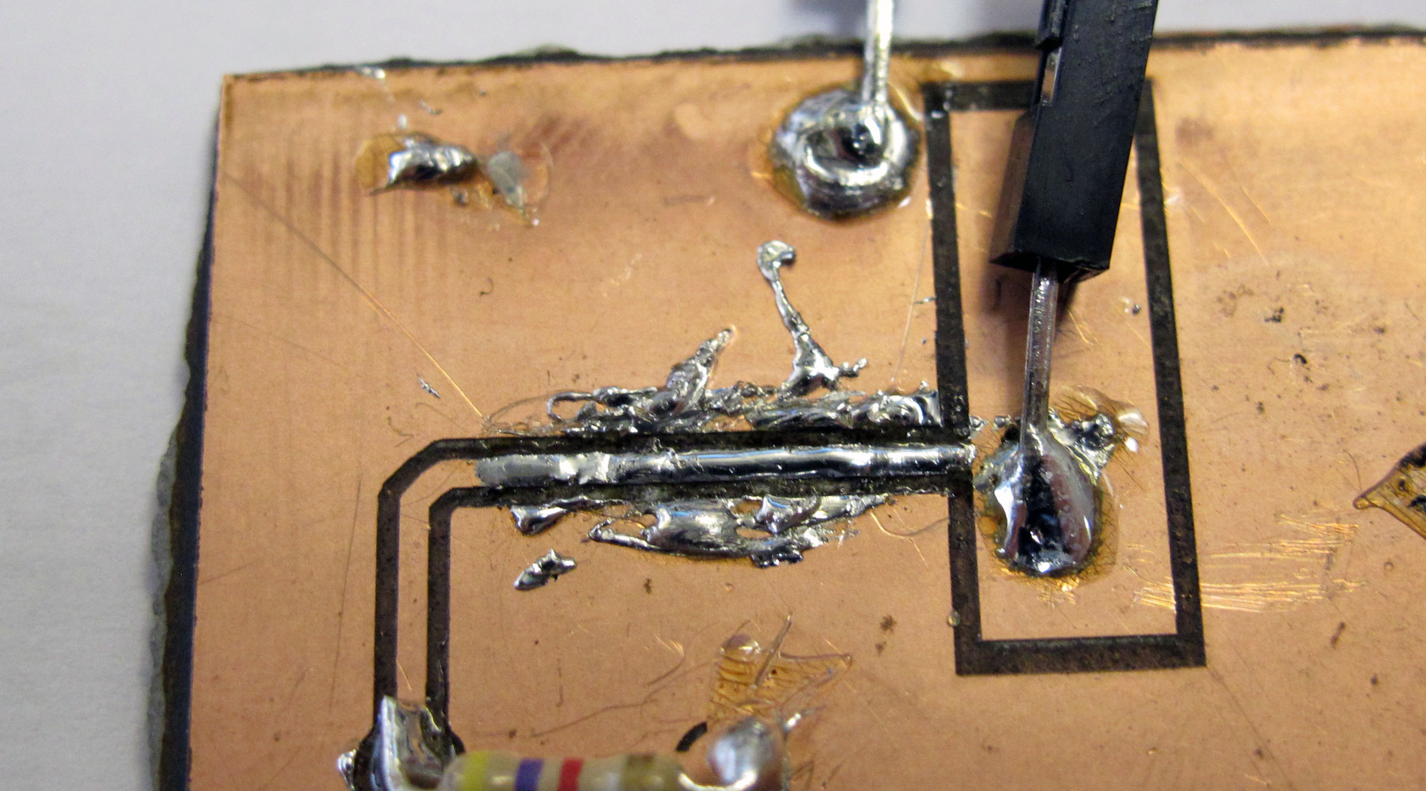
- The ground plane was too close to the signal traces, making soldering through hole components very challenging. The moment the soldering iron touches the ground plane it takes all the heat away from the iron and makes it hard to melt the solder.
2. The 3.5mm audio output jack connection was not done properly.
Also: I have also changed to two potentiometers of a different kind.
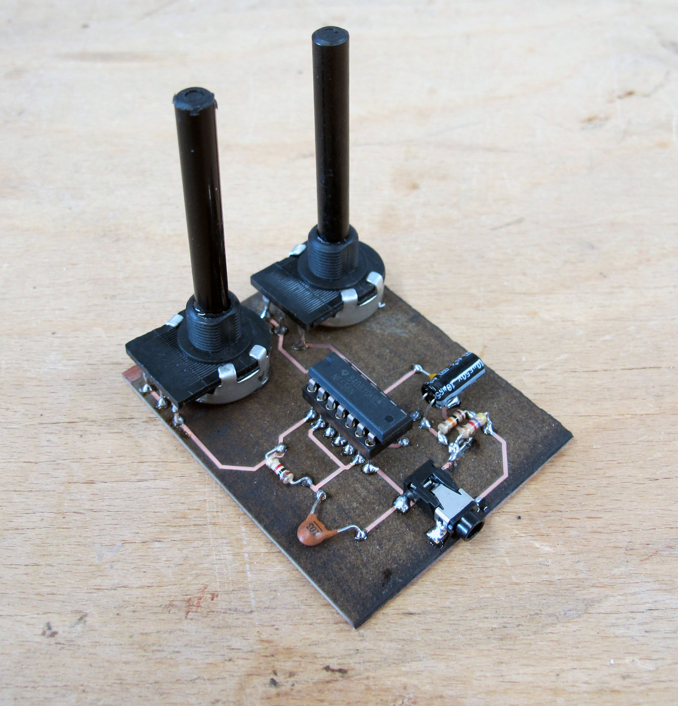
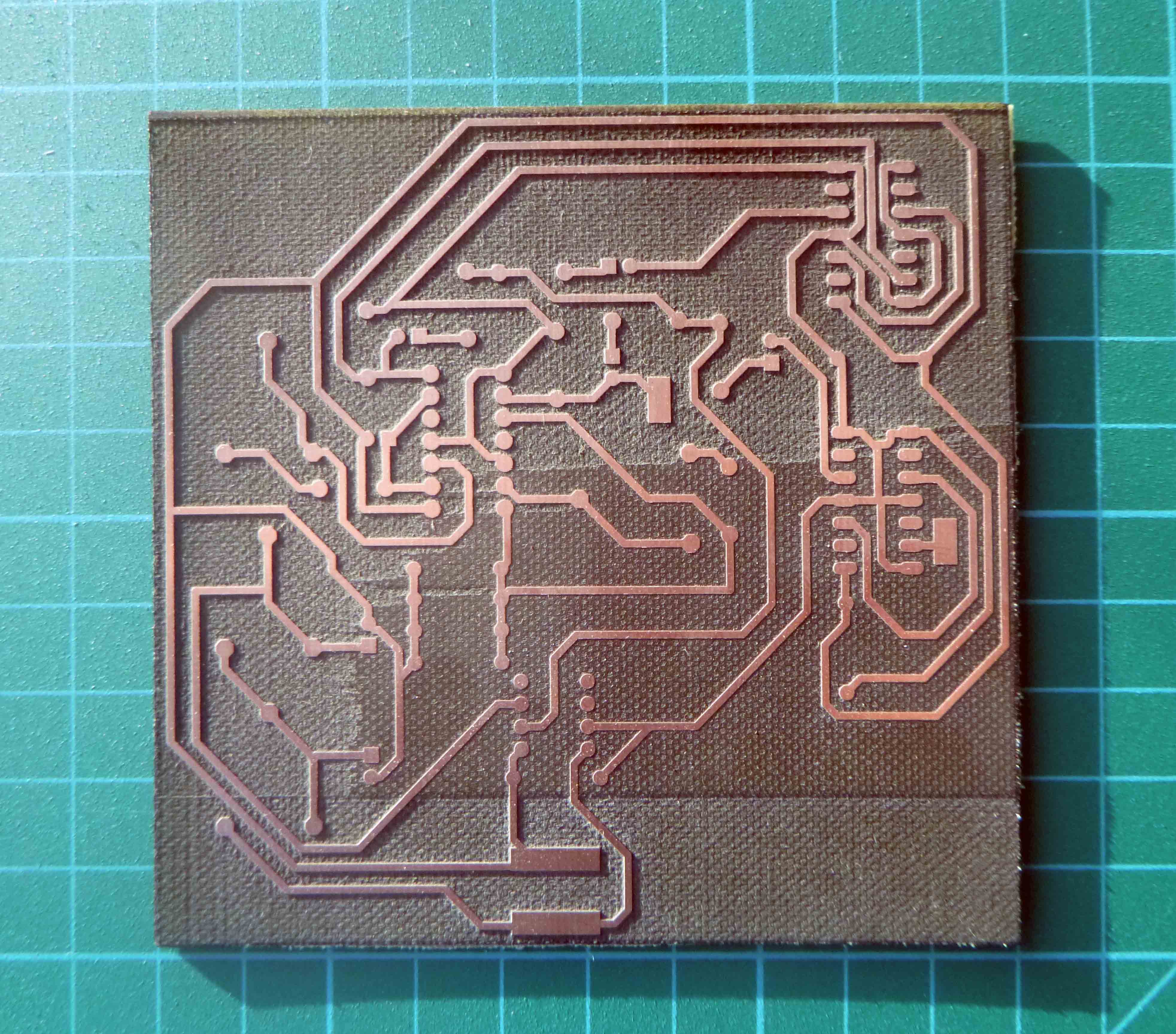
Here is rev.2:
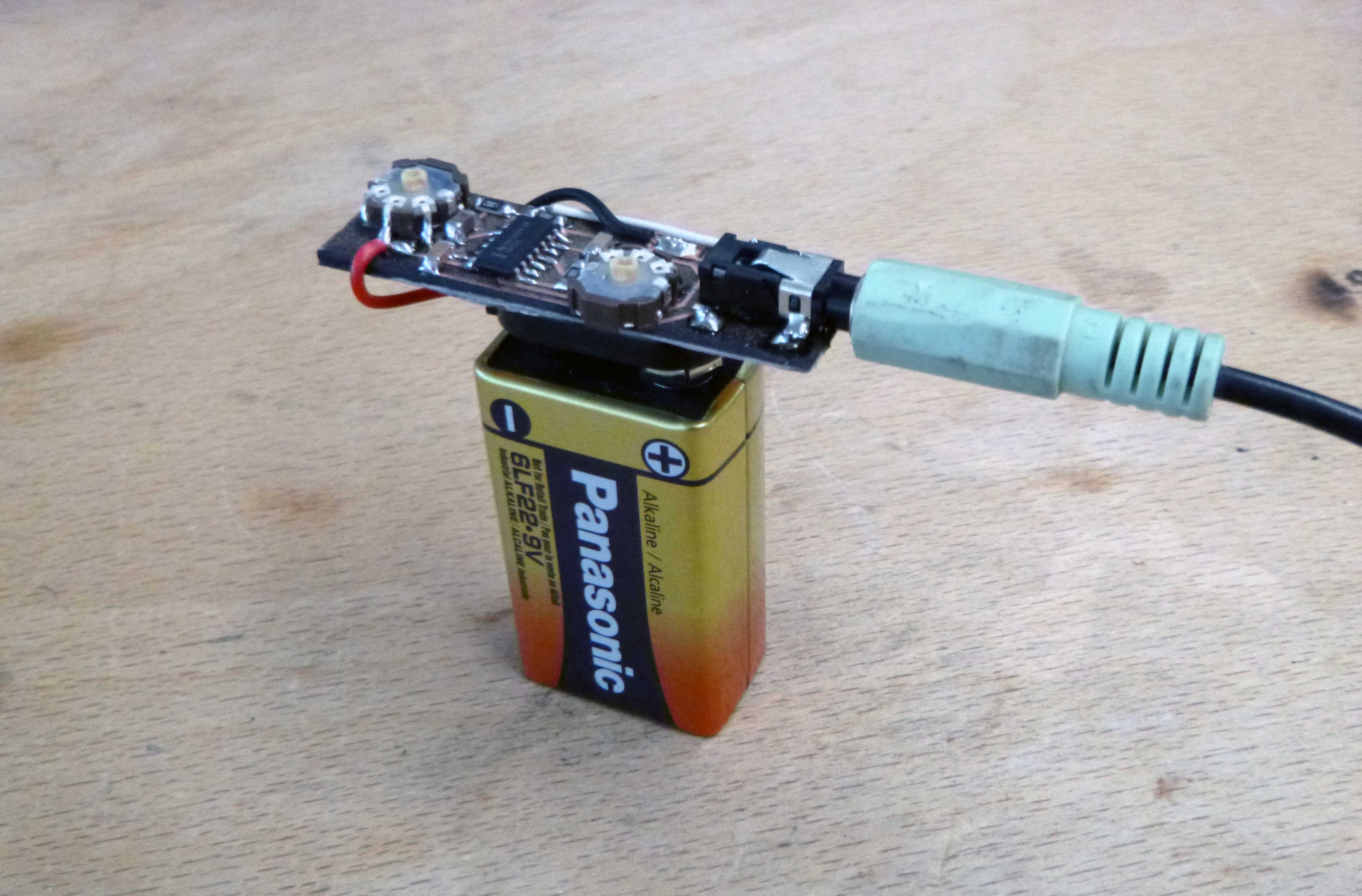
And here is the final product:
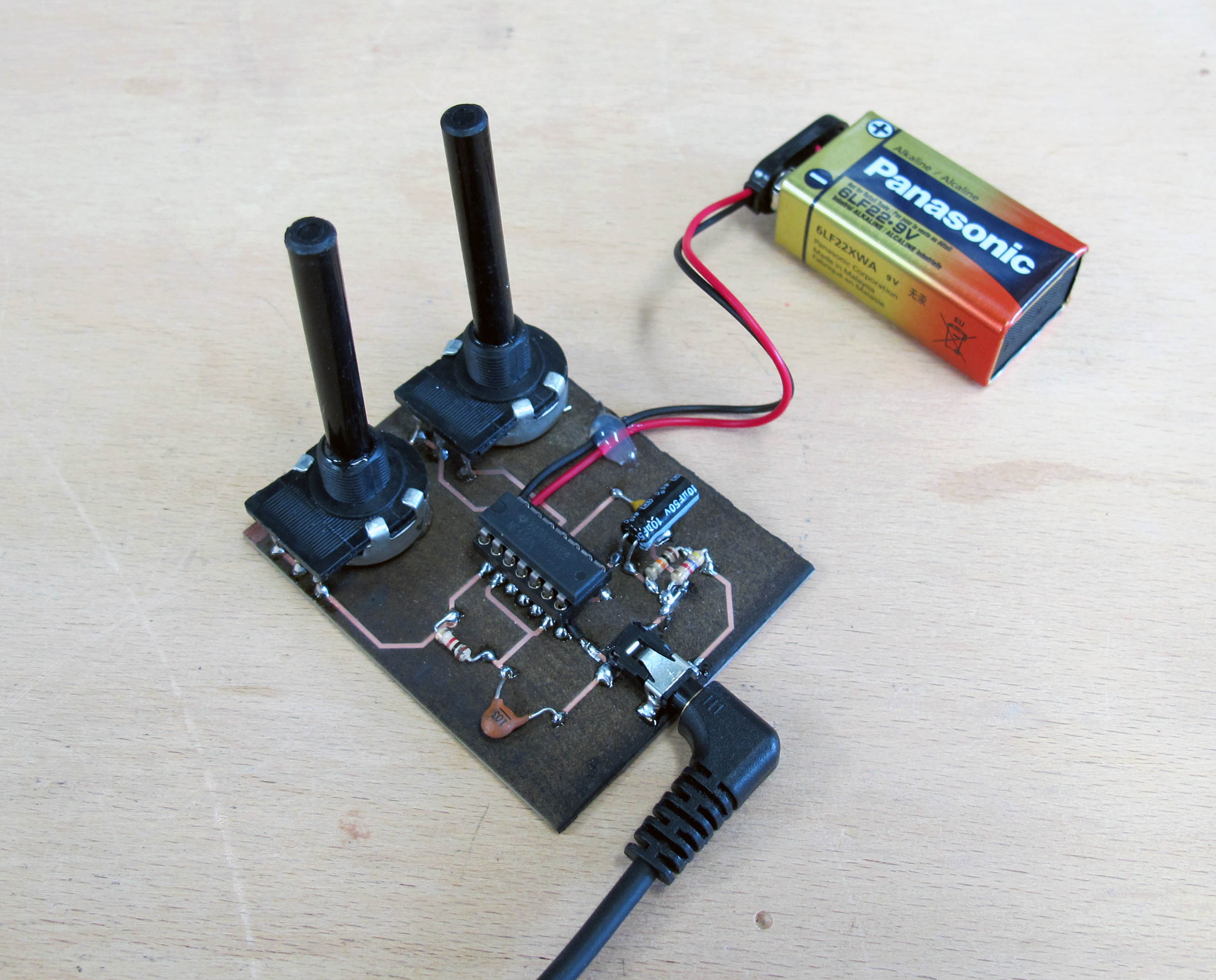
Errata:
I still forgot to make a dignified place for a 9V power connection…Oh well.
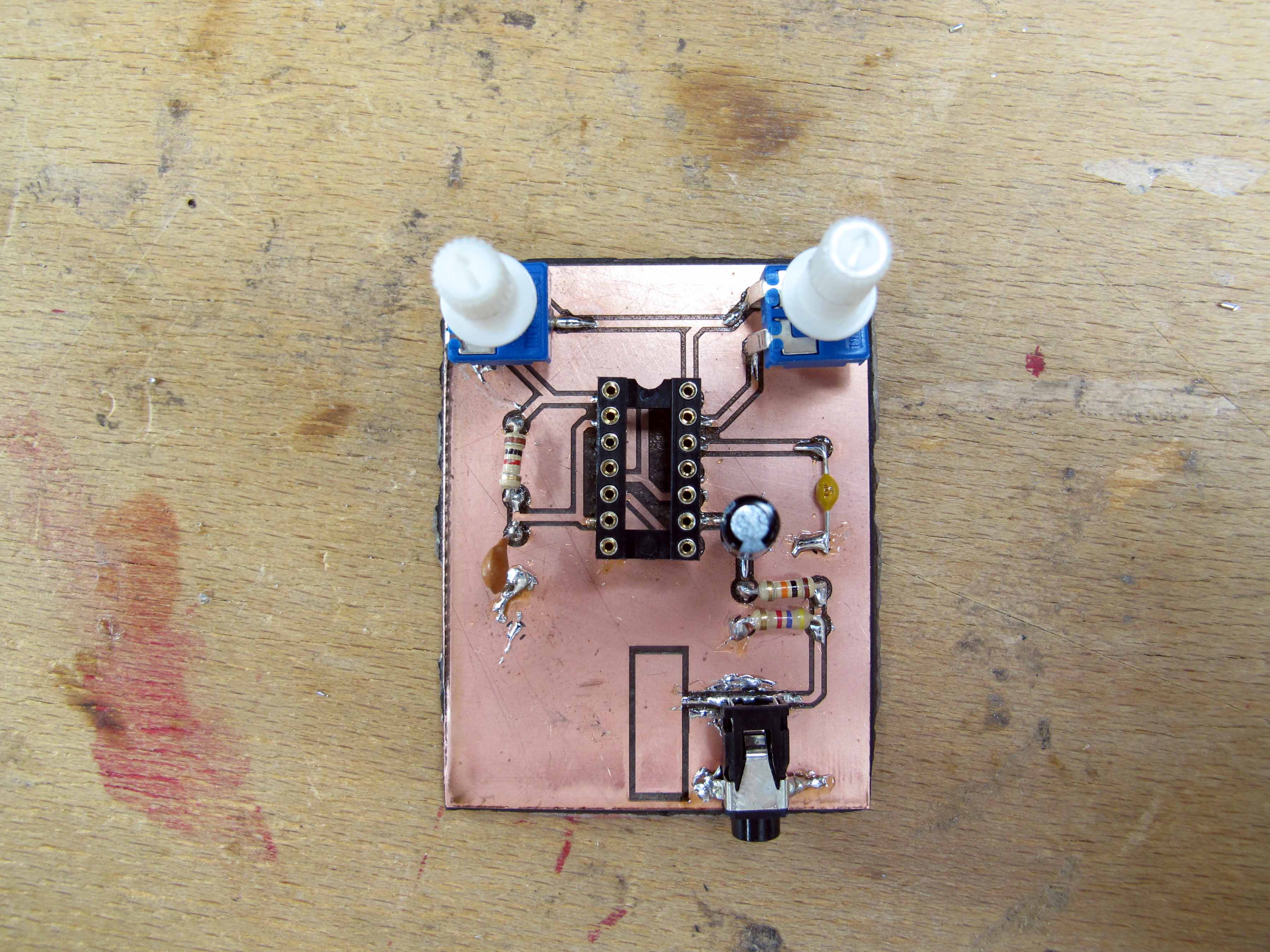
I would like to make a business card version of this circuit, seeing as we have SMD 555 and 556 in the lab!
Here is a first attempt:
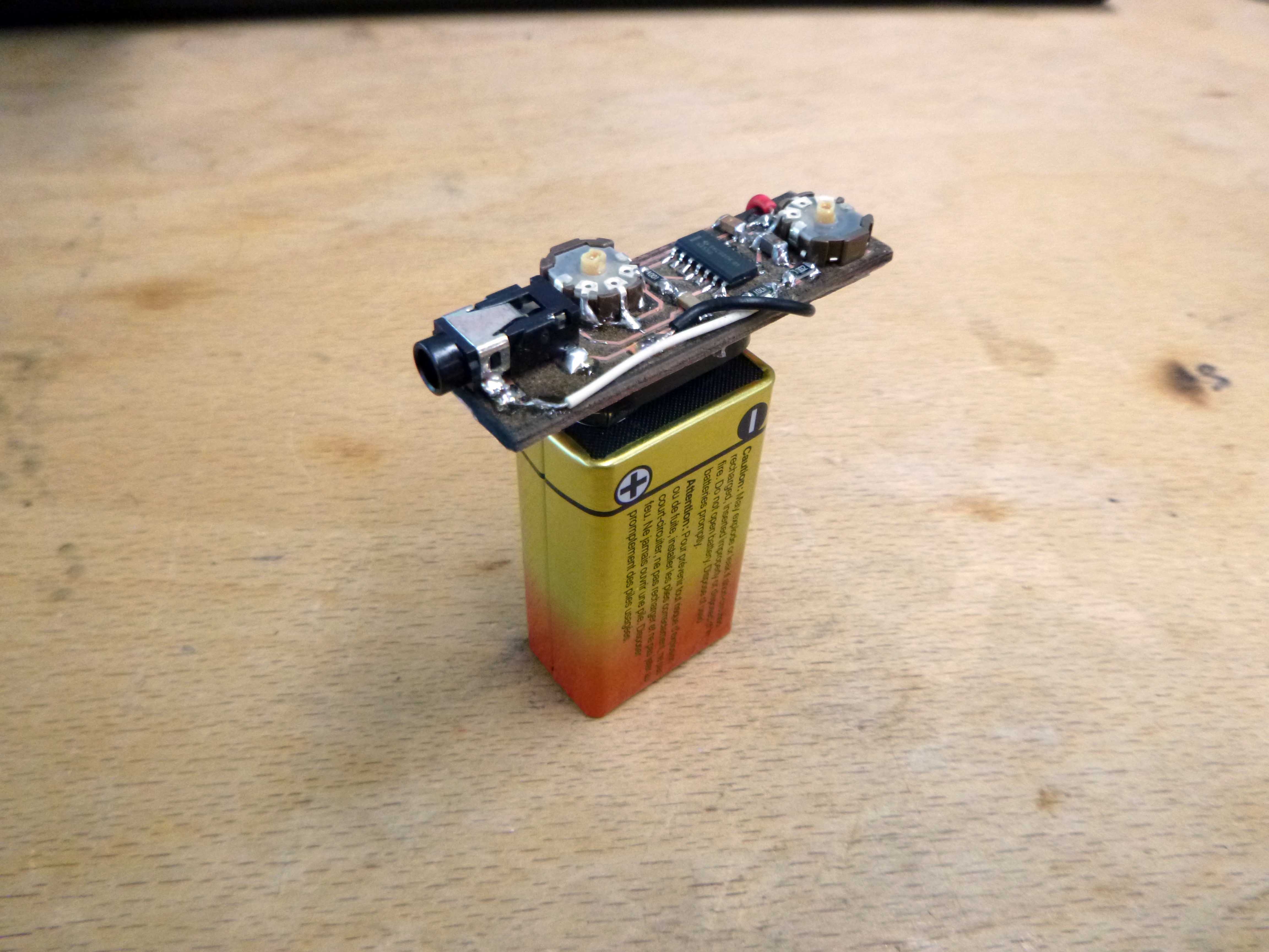
This synth does not currently work. I think it is the replacement of the 1M pots with 50K pots. I am looking at other 556 circuits which don’t require 1M pots (which are hard to find it would seem).
This is from the Spark Punk kit: https://core-electronics.com.au/sparkpunk-sound-kit.html
I started with this circuit then added the other modules in the spark punk kit (except the power and amplication parts).
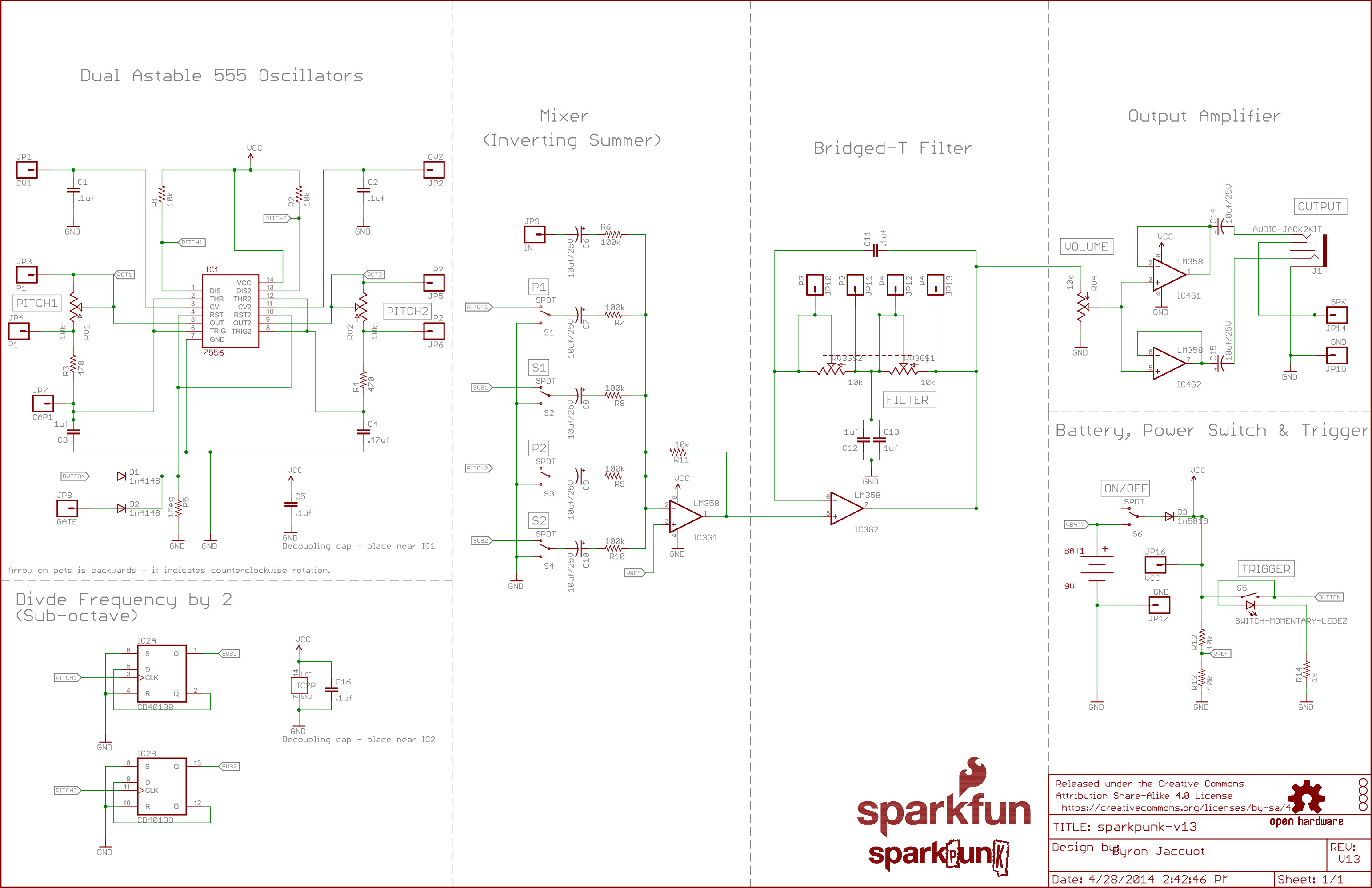
For the frequency dividing I used a JK flip flop 74107 instead of a D-type CD4013 and set it up like so:

I also eliminated the switches in the mixer portion (all the outputs are mixed together all the time) and used an LM386 op amp instead of the LM358.
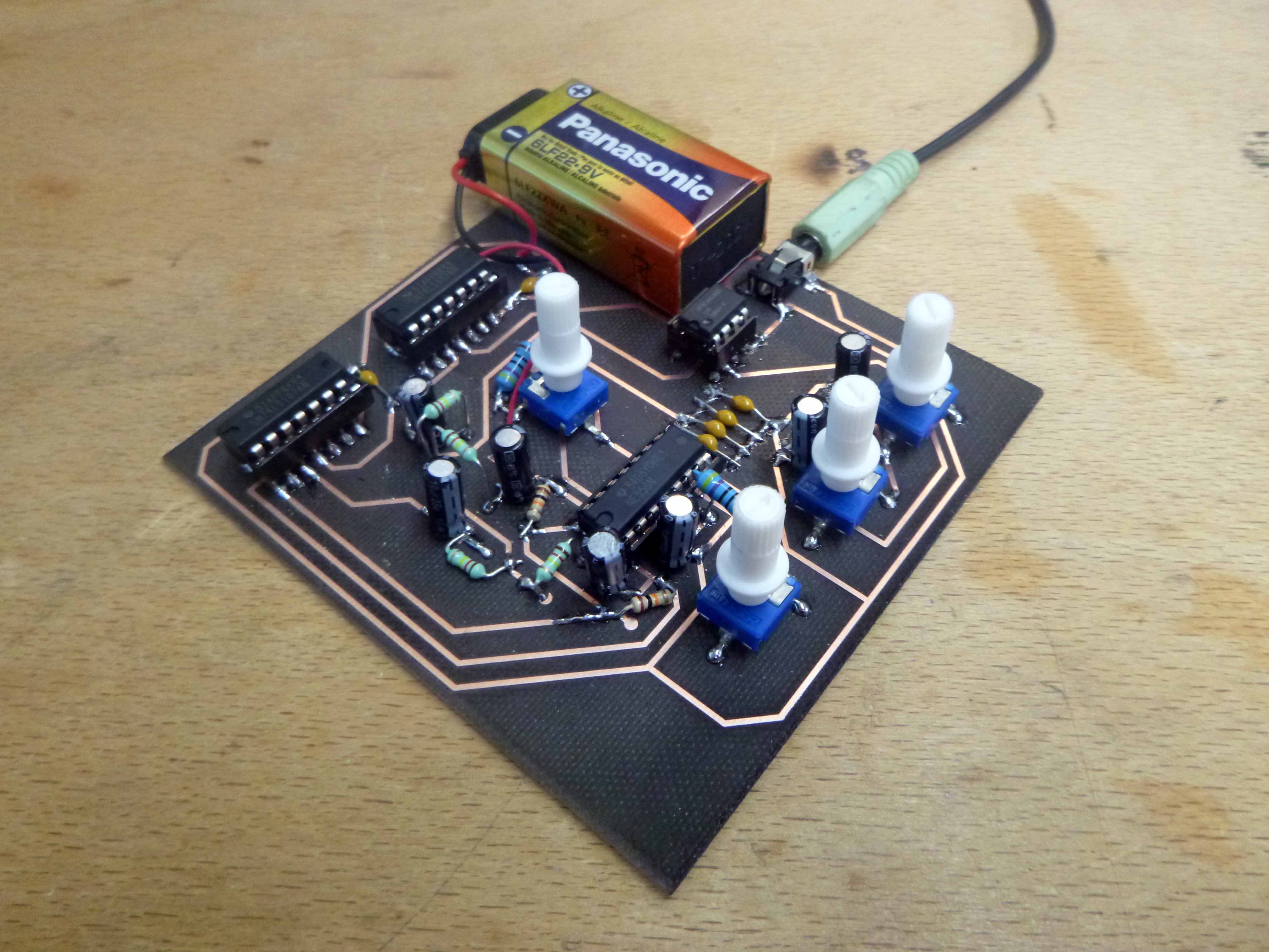
Here is what the circuit looks like set up:
And here is what it sounds like:
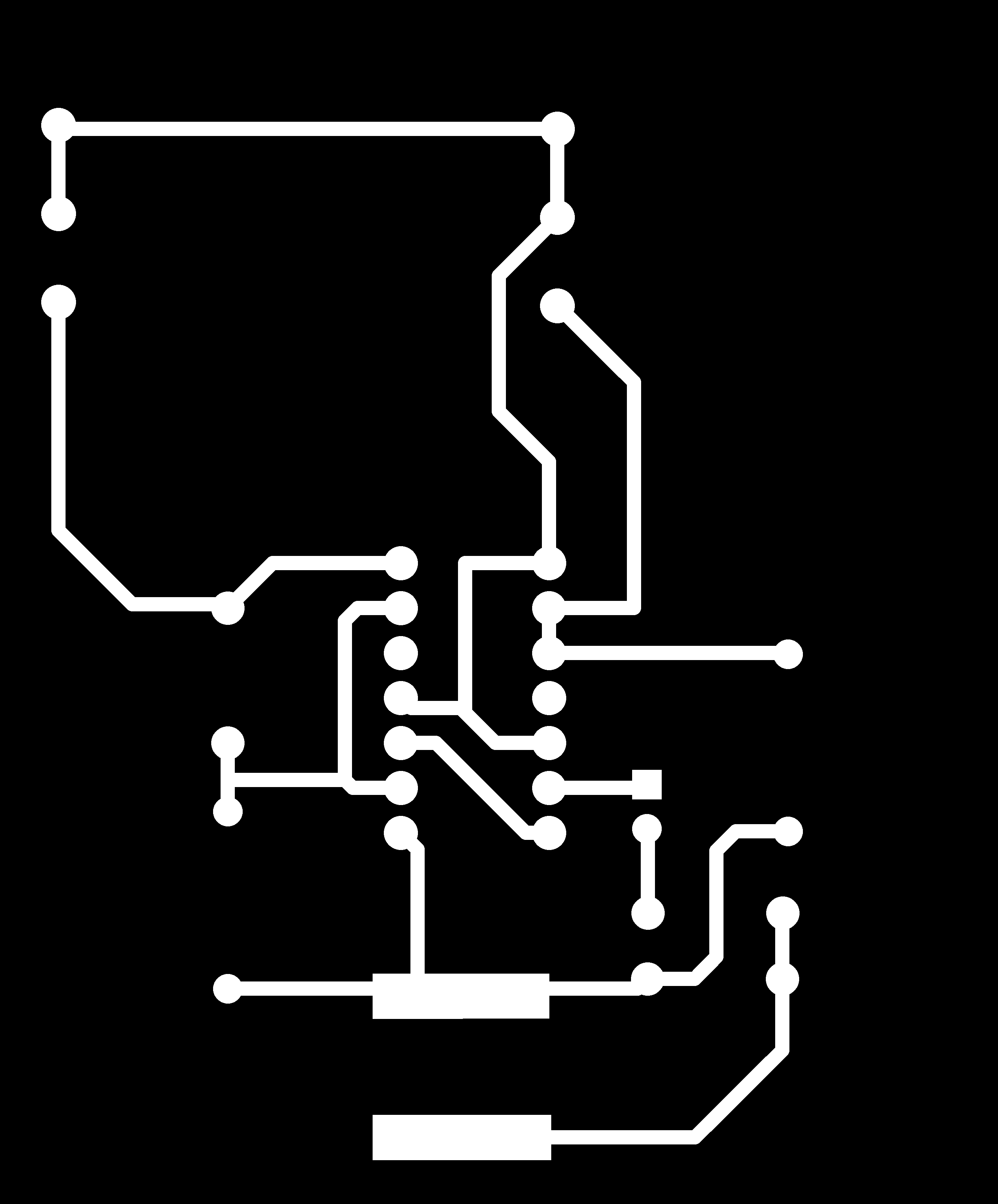
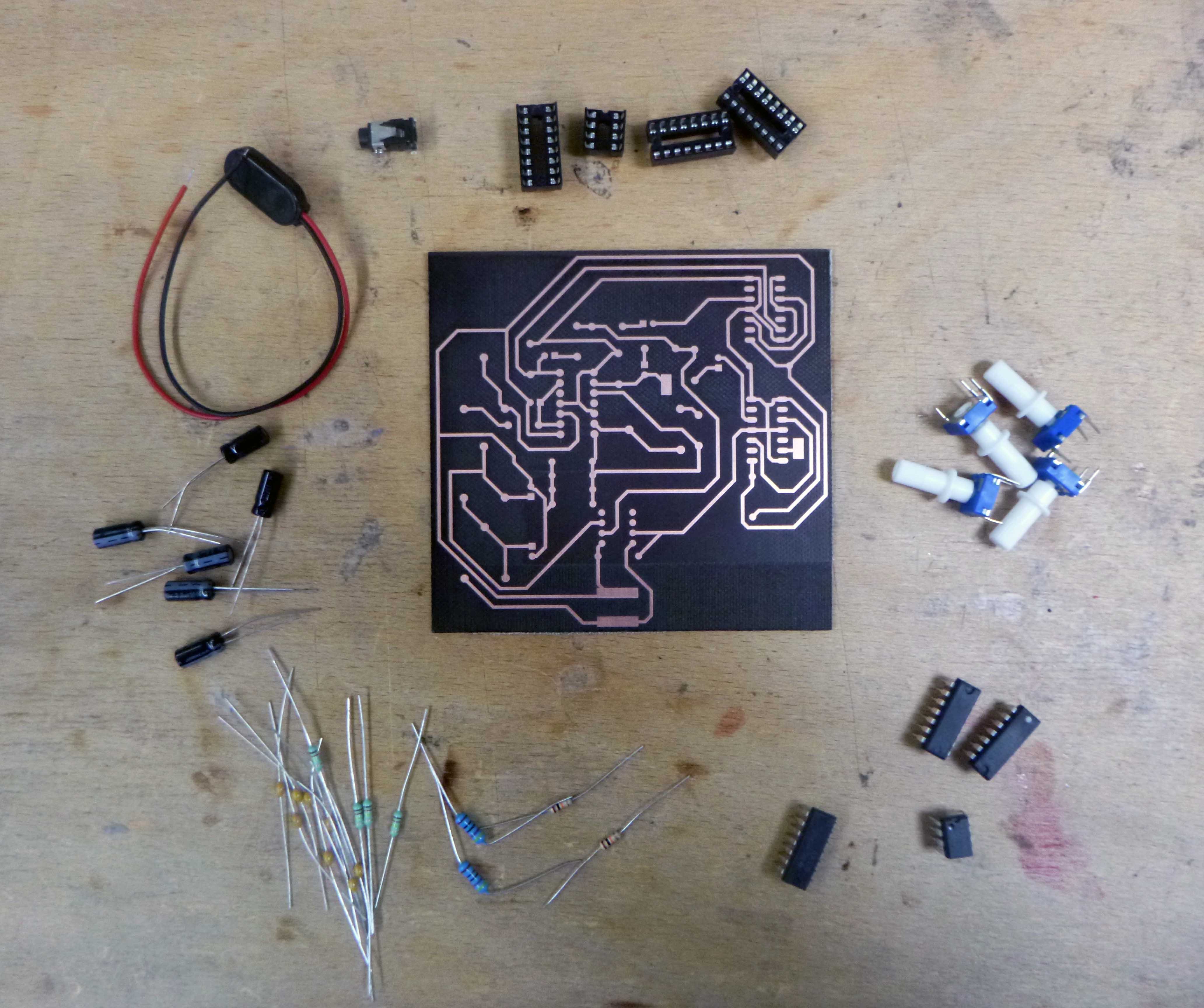
Here is the PCB version before populating:
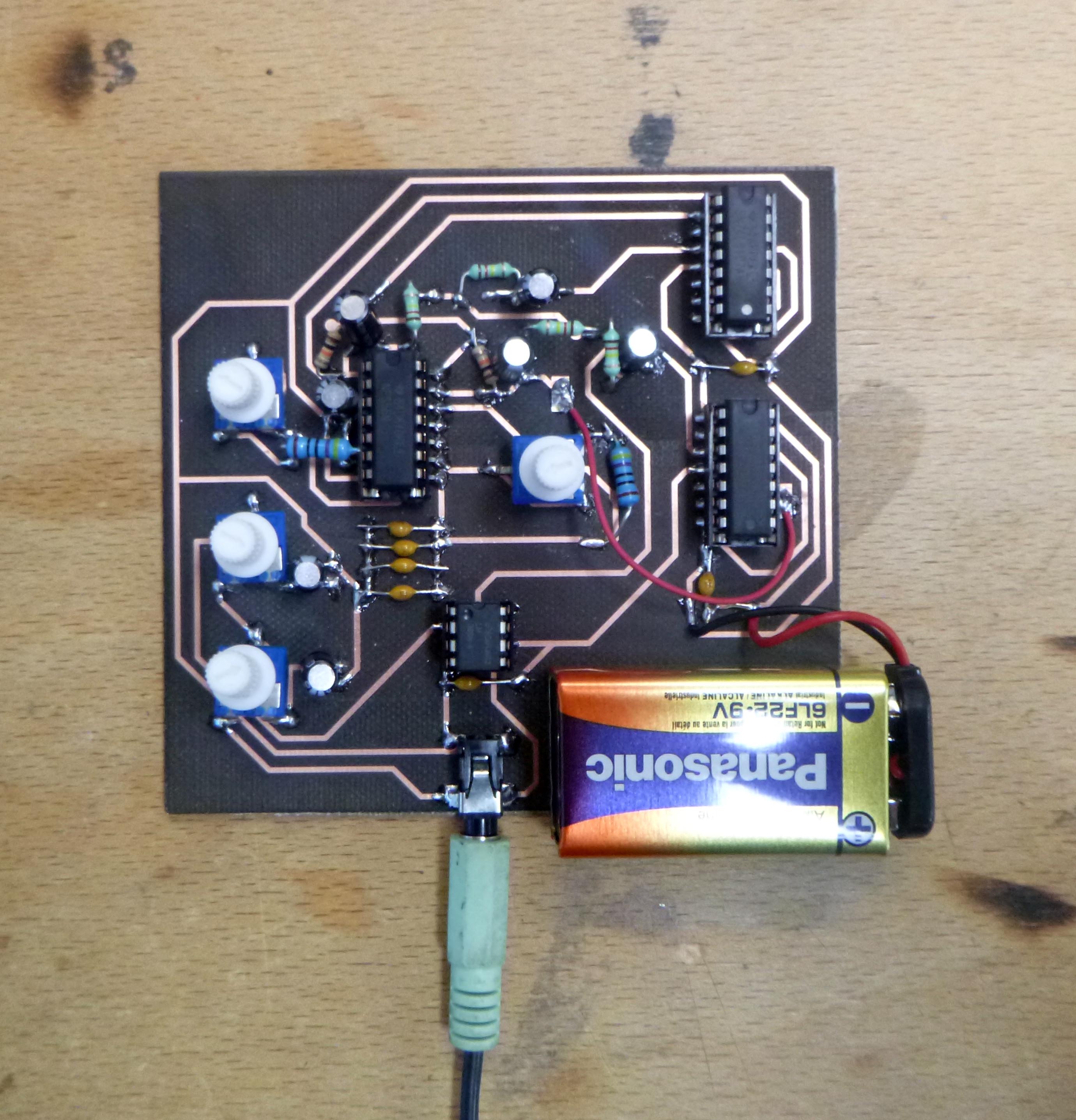
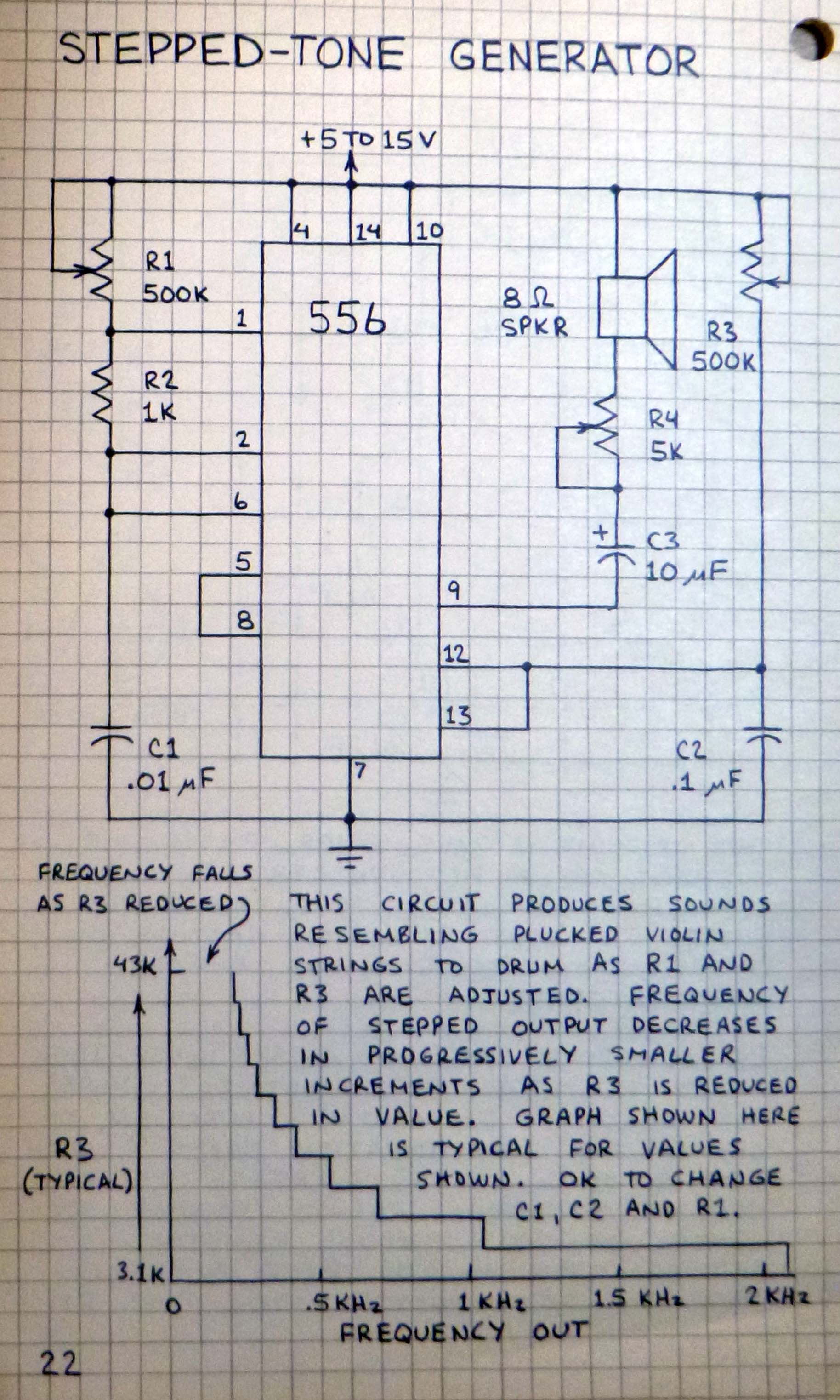
This is from Forrest Mim’s Engineer’s Mini Notebook Stepped-Tone Generator, except I don’t have any 500K pots either…
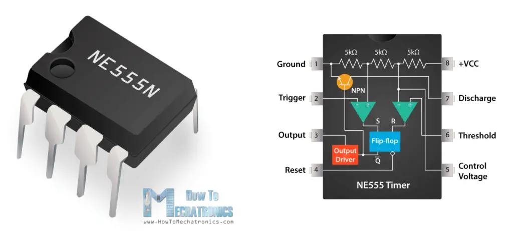
Here is a diagram that helped me understand how the 555 works:
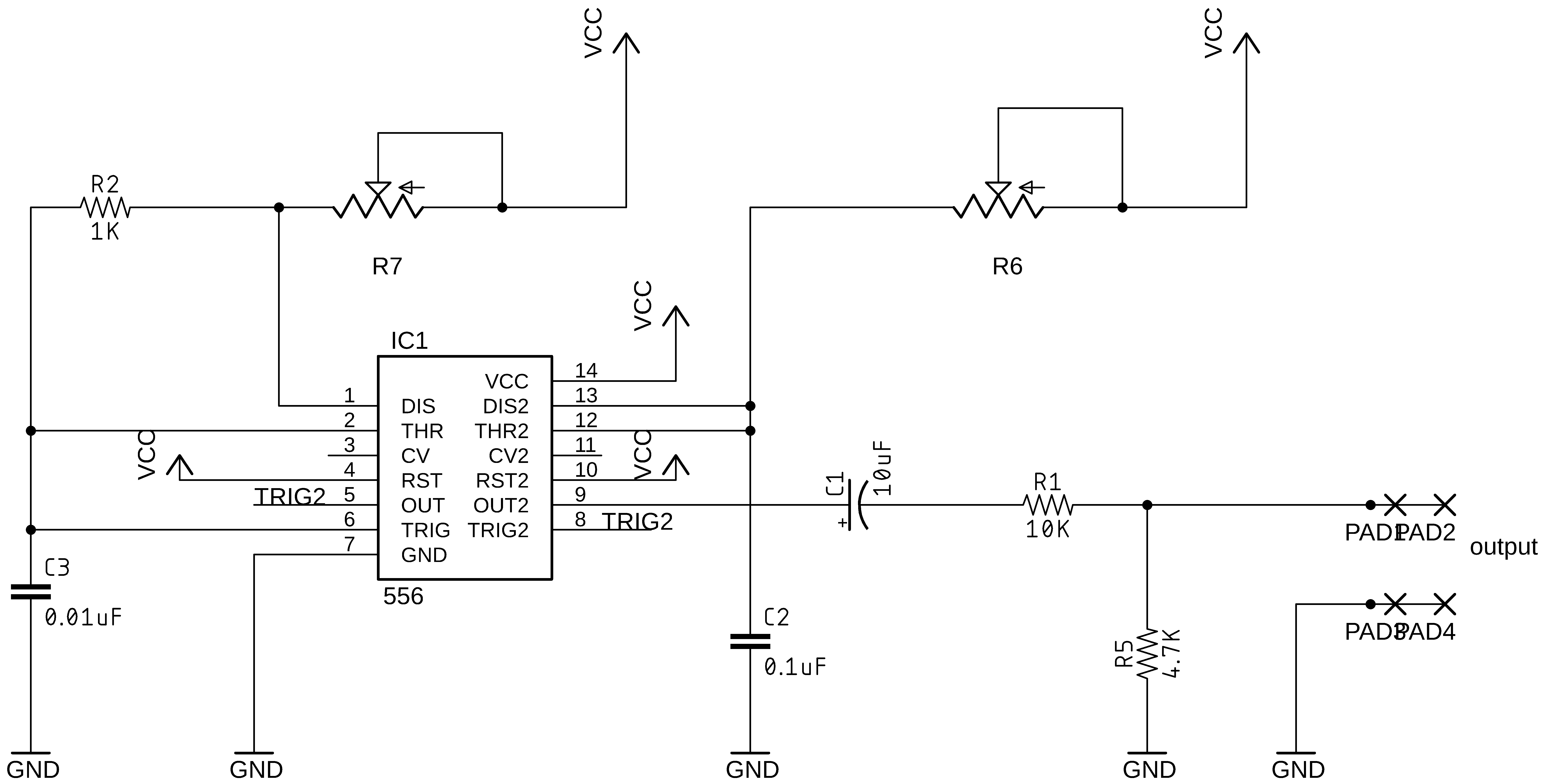
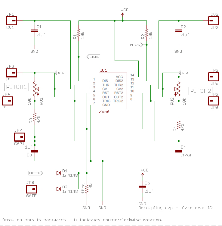
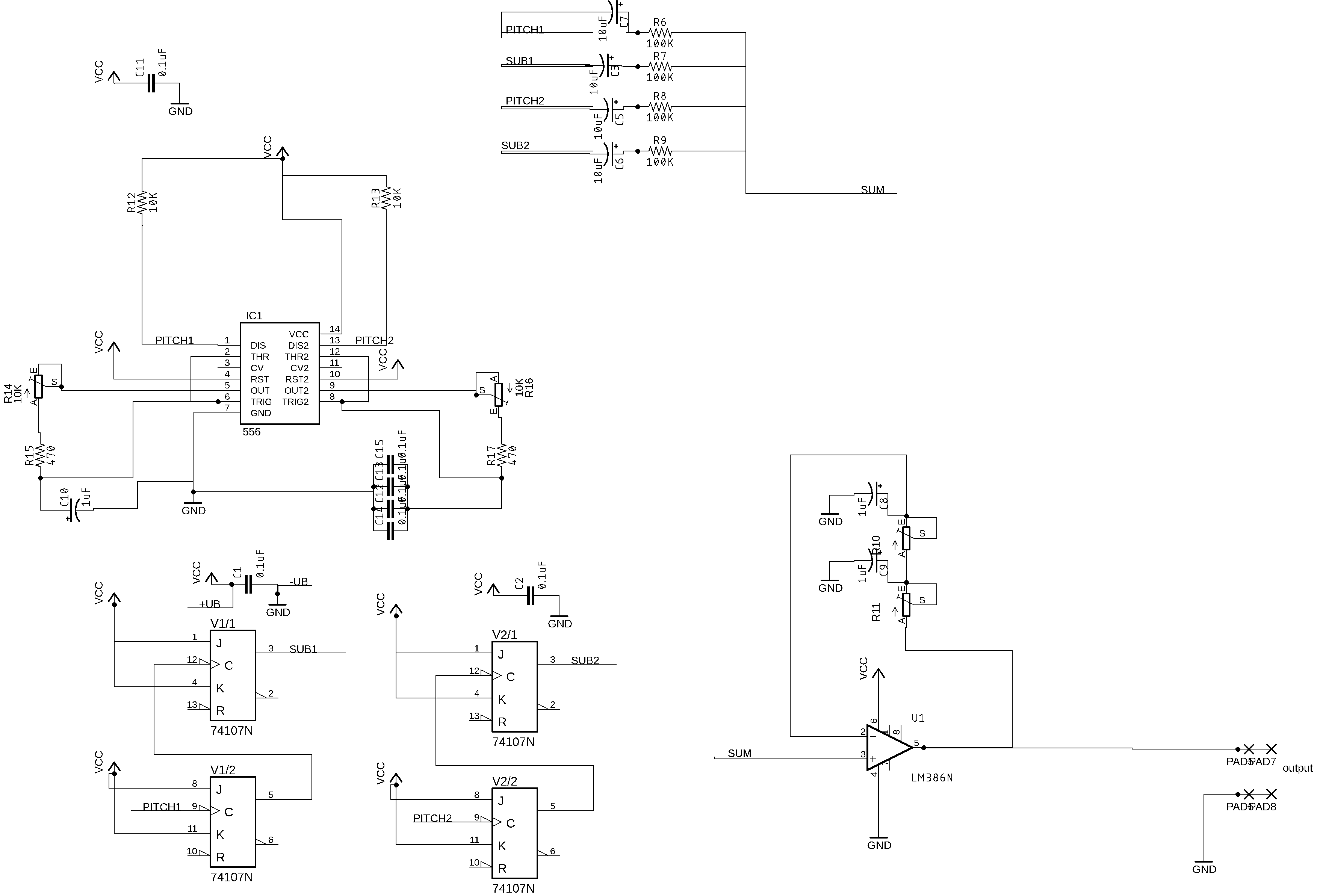
I am now making a PCB version of the sparkpunk design. Here is the schematic (mostly copied from https://cdn.sparkfun.com/datasheets/Kits/sparkpunk-v13.pdf but with changes for the parts I have and simplified for my situation):
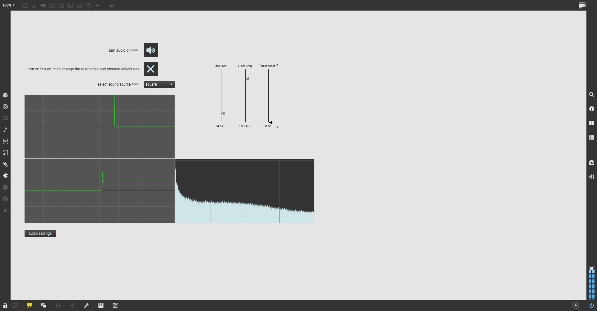
Meanwhile Karl has made a Max 8 patch for me to check out which varies oscillation, filter pass band and resonance (I’m thinking that this means using an inductor to make a filter):
Some important other modules:
noise + sample and hold (check the Art of Electronics)
an envelope generator (allows control of Attack, Sustain, Decay and Release.

Here is one simple design for just attack and decay from https://synthnerd.files.wordpress.com/:
